JLG X23J - X700AJ Service Manual User Manual
Page 79
SECTION 3 - CHASSIS & TURNTABLE
3-52
– JLG Lift –
3121448
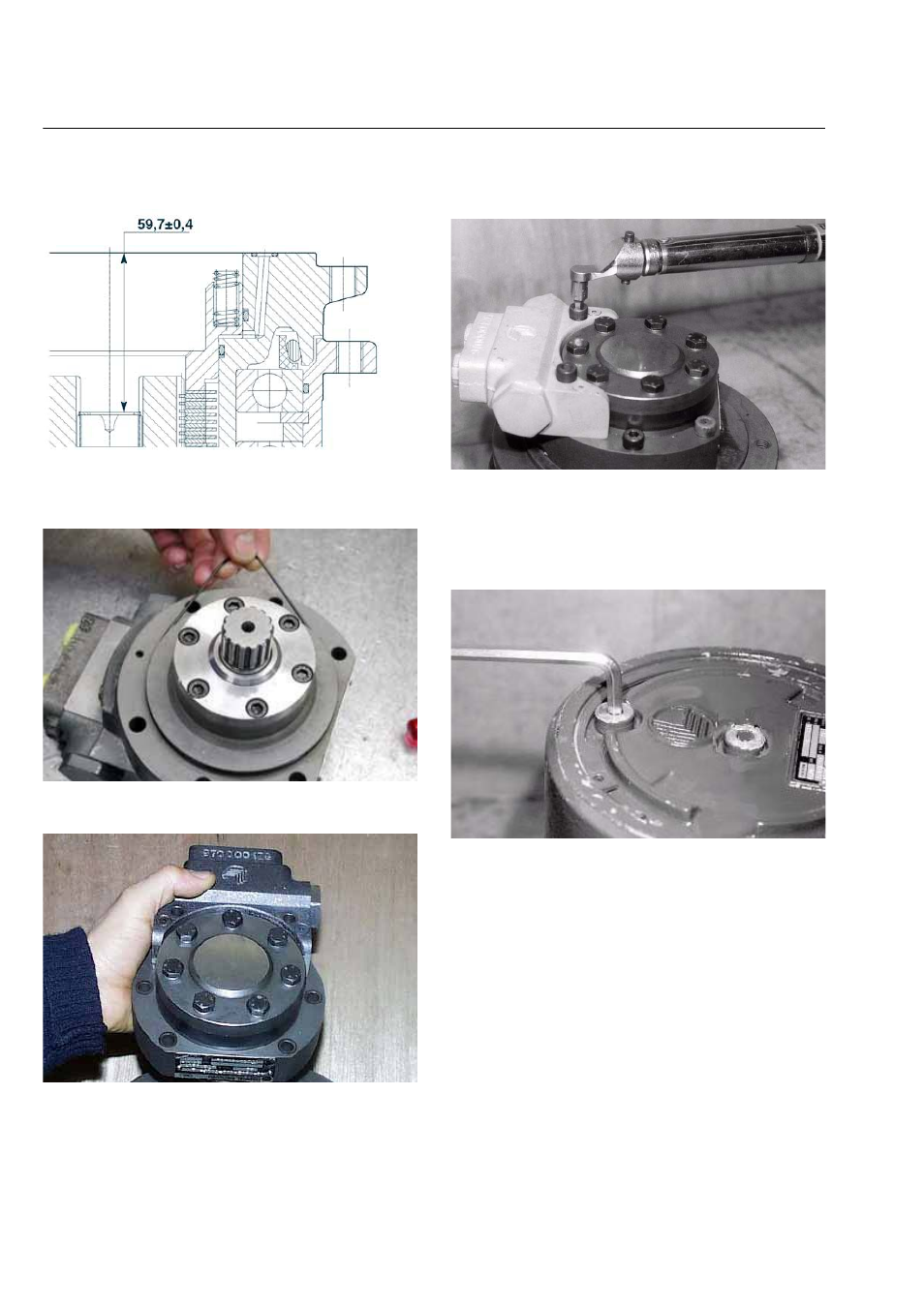
Figure 3-150.
30. Assemble the O-ring seal (28) into the hydraulic
motor seat.
Figure 3-151.
31. Place the hydraulic motor on the flanged hub (15).
Figure 3-152.
32. Fix the hydraulic motor to the gearbox by 4 socket
head screws M8x45 (29) grade 12.9, and by 2
socket head screws M8x75 (54) grade 12.9, tight-
ened by a torque wrench at 42 Nm torque.
Figure 3-153.
33. Fill the gearbox with the lubricant oil as shown in
section 3.4. Insert the washers and the plugs (2) into
the oil draing-filling holes of the end cover
(4).Tighten the plugs by a torque wrench at 10±2
Nm torque.
Figure 3-154.
DISMANTLING AND DESTROYING THE
PRODUCT
When dismantling the gearmotor follow the indications
given below.
a. Remove the gearbox from the machine frame
and let the lubricant oil flow.
b. Completely dismount the gearbox and remove
all oil and grease from its parts.
c. Send all dangerous and/or polluted parts to the
authorised demolishing centres whilst keeping
in line with respective local rules and regula-
tions.