JLG X23J - X700AJ Service Manual User Manual
Page 364
SECTION 3 - CHASSIS & TURNTABLE
3121448
– JLG Lift –
3-337
FUEL TRANSFER PUMP - REMOVE AND INSTALL
(MECHANICAL FUEL TRANSFER PUMP)
REMOVAL PROCEDURE
DO NOT ALLOW DIRT TO ENTER THE FUEL SYSTEM. THOR-
OUGHLY CLEAN THE AREA AROUND A FUEL SYSTEM COMPO-
NENT THAT WILL BE DISCONNECTED. FIT A SUITABLE COVER
OVER DISCONNECTED FUEL SYSTEM COMPONENT.
CARE MUST BE TAKEN TO ENSURE THAT FLUIDS ARE CON-
TAINED DURING PERFORMANCE OF INSPECTION, MAINTE-
NANCE, TESTING, ADJUSTING AND REPAIR OF THE PRODUCT.
BE PREPARED TO COLLECT THE FLUID WITH SUITABLE CON-
TAINERS BEFORE OPENING ANY COMPARTMENT OR DISASSEM-
BLING ANY COMPONENT CONTAINING FLUIDS. DISPOSE OF ALL
FLUIDS ACCORDING TO LOCAL REGULATIONS AND MANDATES.
KEEP ALL PARTS CLEAN FROM CONTAMINANTS. CONTAMI-
NANTS MAY CAUSE RAPID WEAR AND SHORTENED COMPONENT
LIFE.
NOTE: Place identification marks on all hoses for installation
purposes. Plug all hoses and all the ports in the fuel
transfer pump. This helps prevent fluid loss, and this
helps to keep contaminants from entering the sys-
tem.
1. Turn the fuel supply to the OFF position.
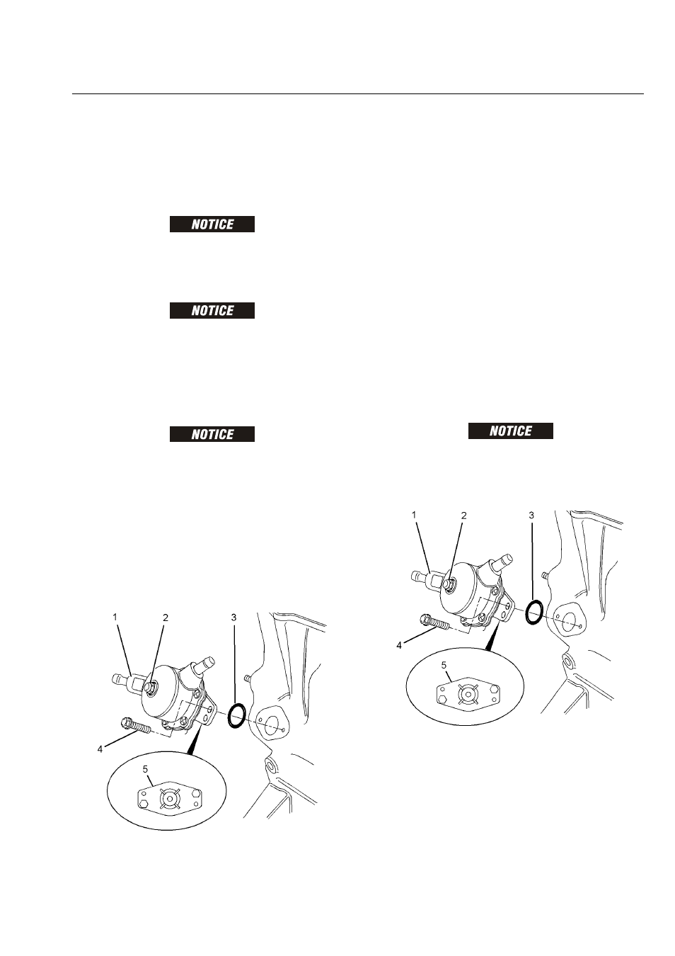
NOTE: The fuel transfer pump can be oriented in two posi-
tions. Before removing the fuel transfer pump from
the cylinder block, note the orientation of flange (5)
on fuel transfer pump (1) for assembly.
2. Loosen the hose clamps and disconnect the hoses
(not shown) from fuel transfer pump (1).
3. Evenly loosen bolts (4) and remove fuel transfer
pump (1) from the cylinder block.
NOTE: In order to remove the fuel transfer pump, it may be
necessary to rotate the crankshaft until the operating
plunger of the fuel transfer pump is not under pres-
sure.
4. Remove O-ring seal (3) from fuel transfer pump (1).
INSTALLATION PROCEDURE
KEEP ALL PARTS CLEAN FROM CONTAMINANTS. CONTAMI-
NANTS MAY CAUSE RAPID WEAR AND SHORTENED COMPONENT
LIFE.
1. Clean the mating surfaces of the cylinder block and
flange (5) on the fuel transfer pump.
NOTE: Ensure that the camshaft lobe for the fuel transfer
pump is at minimum lift before the fuel transfer pump
is installed. The fuel transfer pump can be oriented