JLG X23J - X700AJ Service Manual User Manual
Page 383
SECTION 3 - CHASSIS & TURNTABLE
3-356
– JLG Lift –
3121448
INSTALLATION PROCEDURE
KEEP ALL PARTS CLEAN FROM CONTAMINANTS. CONTAMI-
NANTS MAY CAUSE RAPID WEAR AND SHORTENED COMPONENT
LIFE.
MAKE SURE THAT THE COMPONENTS OF THE BREATHER
ASSEMBLY ARE INSTALLED CORRECTLY. ENGINE DAMAGE MAY
OCCUR IF THE BREATHER ASSEMBLY IS NOT WORKING PROP-
ERLY.
The two cylinder, the three cylinder and the four cylinder
engines have different crankcase breathers. The installa-
tion procedure is similar for all models.
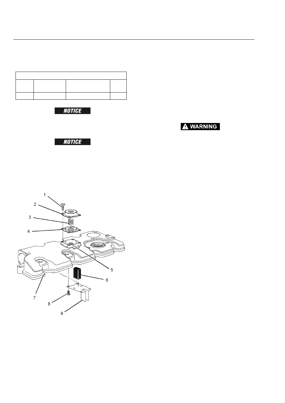
1. Clean all parts and inspect all parts. Replace any
parts that are worn or damaged. Ensure that the
cavity for the breather in the valve mechanism cover
is clean. Ensure that vent hole (5) and the vent hole
in cover (2) are free from restriction.
2. If necessary, follow Steps 2.a through 2.d in order to
install the gauze for the breather.
a. Install gauze (6) to valve mechanism cover (7).
b. Position plate (9) on valve mechanism cover (7)
and install screws (8).
c. Tighten screws (8) to a torque of 1.5 N·m (13 lb
in).
d. Install valve mechanism cover (7). Refer to Dis-
assembly and Assembly, “Valve Mechanism
Cover - Remove and Install” for the correct pro-
cedure.
PERSONAL INJURY CAN RESULT FROM BEING STRUCK BY
PARTS PROPELLED BY A RELEASED SPRING FORCE. MAKE
SURE TO WEAR ALL NECESSARY PROTECTIVE EQUIPMENT. FOL-
LOW THE RECOMMENDED PROCEDURE AND USE ALL RECOM-
MENDED TOOLING TO RELEASE THE SPRING FORCE.
3. Install diaphragm (4) and spring (3) to cover (2).
4. Position the assembly of cover (2), spring (3) and
diaphragm (4) onto valve mechanism cover (7).
NOTE: Ensure the correct orientation of the cover.
5. Install bolts (1). Use Tooling (A) in order to tighten
bolts to a torque of 3 N·m (27 lb in).
Required Tools
Tool
Part
Number
Part Description
Qty
A
27610296
Torque Wrench
1