JLG X23J - X700AJ Service Manual User Manual
Page 370
SECTION 3 - CHASSIS & TURNTABLE
3121448
– JLG Lift –
3-343
INSTALLATION PROCEDURE
KEEP ALL PARTS CLEAN FROM CONTAMINANTS. CONTAMI-
NANTS MAY CAUSE RAPID WEAR AND SHORTENED COMPONENT
LIFE.
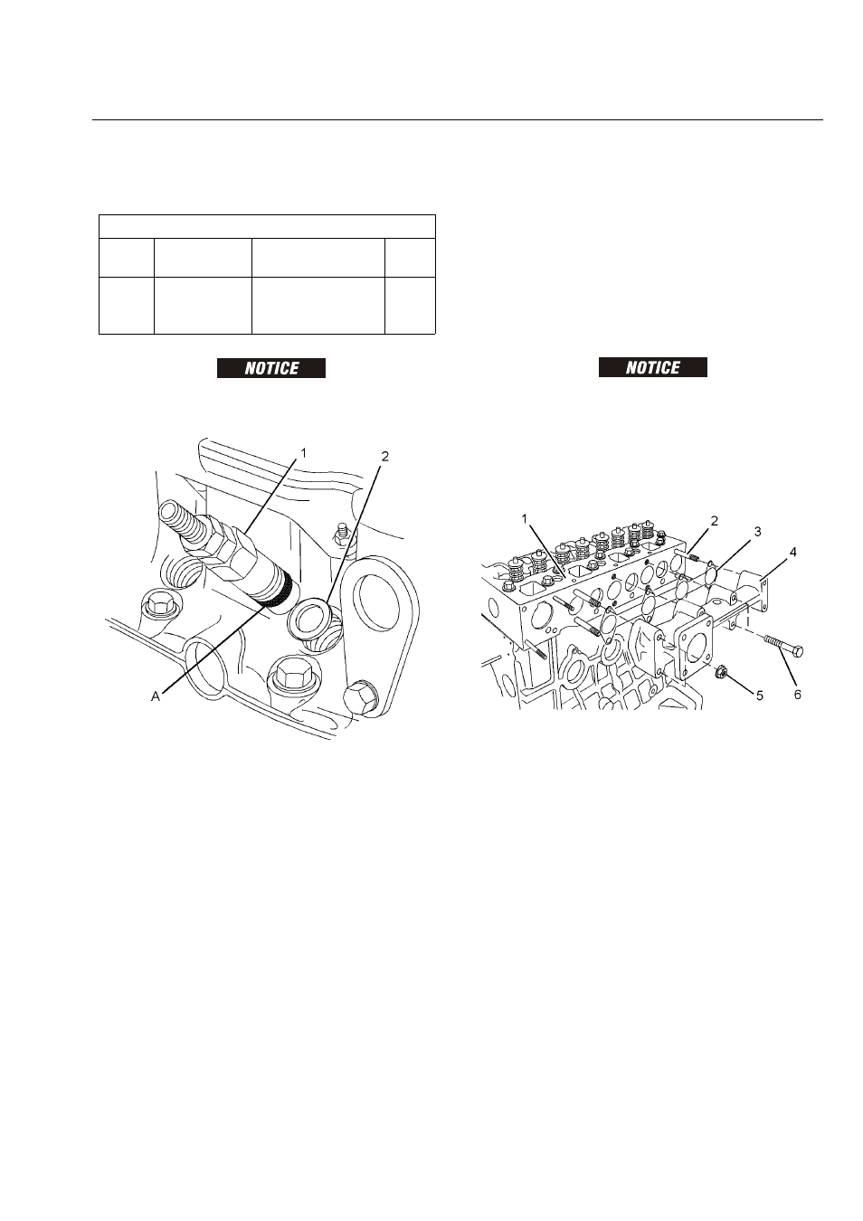
1. Clean the bore for the fuel injector in the cylinder
head. Ensure that no debris enters the cylinder.
Clean the threads on the body of the fuel injector.
2. Install new seat washers (2) into the bore for the fuel
injector in the cylinder head.
NOTE: 402D-05 and 403D-07 engines have two seat wash-
ers. The seat washers are different diameters.
3. Apply a bead of Tooling (A) to the first two threads of
the fuel injector that engage into the cylinder head.
The bead should have a diameter of 2 mm (0.08
inch) and a length of 6 mm (0.25 inch).
NOTE: Ensure that Tooling (A) does not cover the body of
the fuel injector below the threads.
4. Install fuel injector (1) into the cylinder head. Use a
deep socket to tighten the fuel injector to a torque of
64 N·m (47 lb ft).
EXHAUST MANIFOLD - REMOVE AND INSTALL
REMOVAL PROCEDURE
Start By:
a. If the engine is equipped with a turbocharger,
remove the turbocharger. Refer to Disassembly
and Assembly, “Turbocharger, Remove and
Install”.
KEEP ALL PARTS CLEAN FROM CONTAMINANTS. CONTAMI-
NANTS MAY CAUSE RAPID WEAR AND SHORTENED COMPONENT
LIFE.
NOTE: The two cylinder, the three cylinder and the four cyl-
inder engines have different exhaust manifolds. The
removal procedure is similar for all models.
1. Loosen nuts (5) and bolts (6).
NOTE: In order to prevent distortion of the exhaust manifold,
loosen the outer fasteners first.
2. Remove nuts (5) and bolts (6).
NOTE: Identify bolts of different lengths so that the bolts can
be installed in the correct positions.
3. Remove exhaust manifold (4) from cylinder head (1).
Note the orientation of the exhaust manifold for
installation.
4. Remove gasket (3) from cylinder head (1).
5. If necessary, remove exhaust manifold studs (2)
from cylinder head (1).
Required Tools
Tool
Part
Number
Part Description
Qty
A
1861117
POWERPART
Universal Jointing
Compound
1