JLG X23J - X700AJ Service Manual User Manual
Page 402
SECTION 4 - BOOM & PLATFORM
3121448
– JLG Lift –
4-3
6. Using suitable lifting equipment, slide fly boom sec-
tion out to gain access to telescope cylinder attach
pin hole.
7. Measure the distance between the telescope cylin-
der port block attach point on base boom section
and the attach point on fly boom section.
8. Connect a suitable auxiliary hydraulic power source
to the telescope cylinder port block.
9. Extend the telescope cylinder the distance of the
two attach points.
10. Secure the sling and lifting device at the telescope
cylinder’s approximate center of gravity, and lift the
cylinder to the aft end of the boom assembly.
WHEN INSERTING THE TELESCOPE CYLINDER INTO THE BOOM,
CARE MUST BE TAKEN NOT TO DAMAGE THE POWER TRACK
ASSEMBLY.
11. Slowly slide the telescope cylinder into boom
assembly, align rod end with attach point in fly sec-
tion. Insert pin and secure with retaining ring.
12. Slowly slide the telescope cylinder into boom
assembly, align barrel end with attach point in fly
section. Insert pin and secure with retaining ring.
13. Install wear pads at front of base boom section.
Adjust the wear pads to zero clearance.
Figure 4-2.
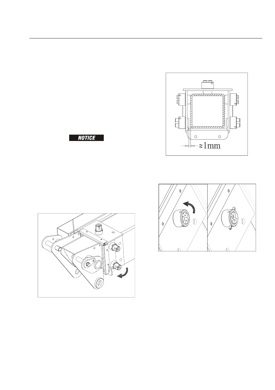
14. Adjust pads alternately side to side, so that fly boom
section is centered in base boom section (lower
wear pad with 1 mm gap).
Figure 4-3.
15. Turn the wear pad to dispose the groove on the
head to insert the cotter.
Figure 4-4.
16. Disconnect auxiliary power source from telescope
cylinder.