JLG X23J - X700AJ Service Manual User Manual
Page 138
SECTION 3 - CHASSIS & TURNTABLE
3121448
– JLG Lift –
3-111
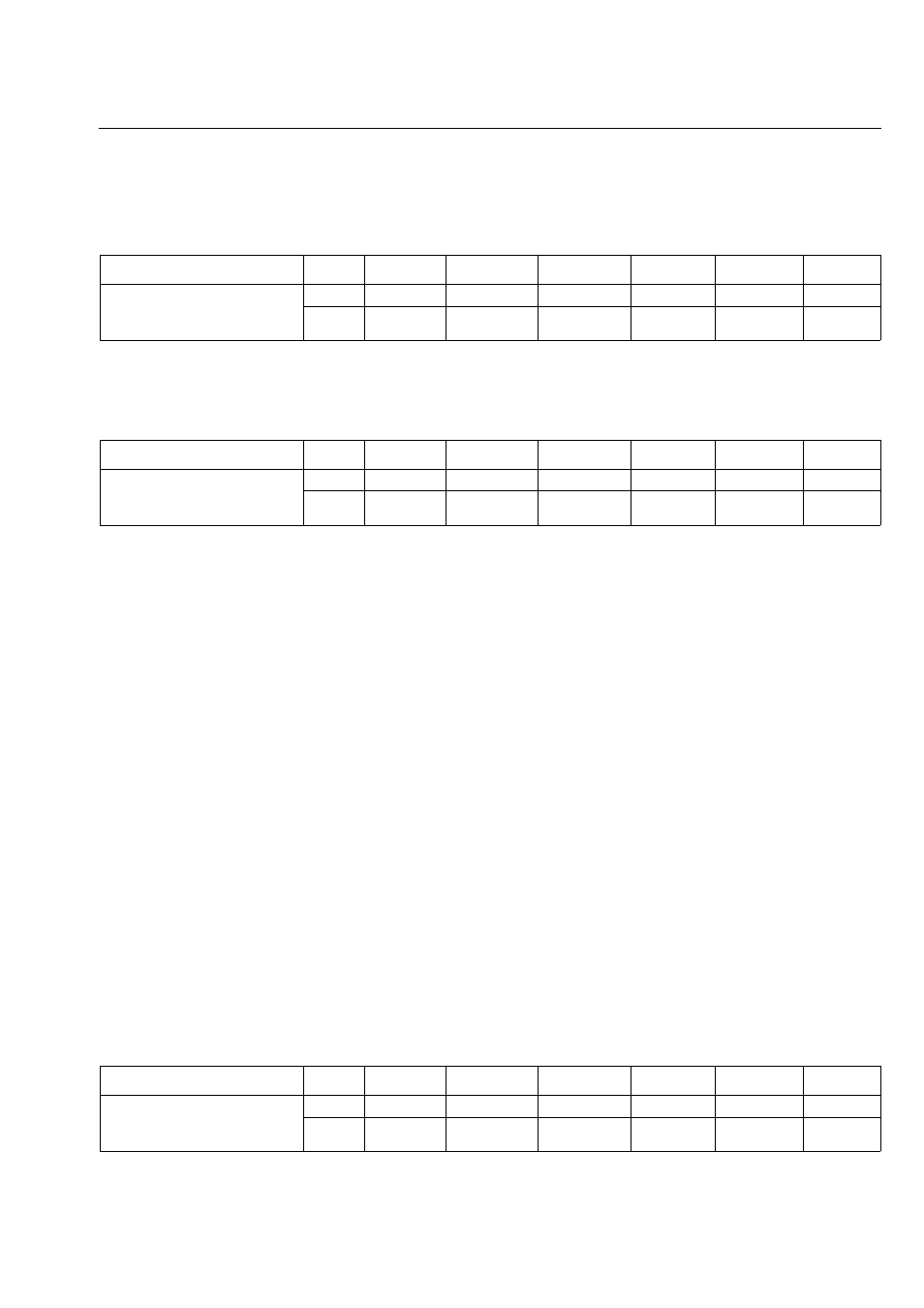
Permissible flatness and perpendicularity deviation for
series WD-L and SP slew drives
Permissible flatness and perpendicularity deviation for
series WD-H slew drives
Determining the deformation of the mounting structure
Under maximum operating load an appropriate deforma-
tion of the mounting structure occurs. The dimensions can
be detected via dial gauges, laser measurement pro-
cesses, or 3D measuring systems.
Because in some cases measurement in operation is diffi-
cult, determination of deformation can also be executed
mathematically, e.g. with the finite element method.
Alternatively you can also reference comparable measure-
ments on test rigs.
FOR SLEW DRIVES THAT ARE BETWEEN THE SPECI-
F I E D S I Z E S , A L W A Y S A S S U M E T H E S M A L L E R
V A L U E . F O R S L E W D R I V E S T H A T A RE L A R G E R
THAN THE LARGEST DIAMETER, USE THE LARGEST
SPECIFIED VALUE.
THE SLEW DRIVE MUST BE SUPPORTED BY THE
MOUN TIN G S TRUC TURE UP TO THE DIAME TER
SPECIFIED IN THE SLEW DRIVE DRAWING. ALL THE
INSTALLED DIMENSIONS AS SPEC IFIED IN THE
DRAWING MUST BE COMPLIED WITH.
Permissible deformation of the mounting structure,
under maximum load for series WD-L and SP slew
drives
Running circle diameter [mm]
≥
100
≥
250
≥
500
≥
750
≥
1000
≥
1250
Permissible flatness deviation
including perpendicularity devia-
tion per support surface
[mm]
0.04
0.06
0.08
0.09
0.10
0.11
[in]
0.0016
0.0024
0.0032
0.0036
0.0040
0.0044
Size of the slew drive
≥
146
≥
220
≥
300
≥
373
≥
490
≥
625
Permissible flatness deviation
including perpendicularity devia-
tion per support surface
[mm]
0.06
0.06
0.07
0.07
0.08
0.09
[in]
0.0024
0.0024
0.0028
0.0028
0.0032
0.0036
Running circle diameter [mm]
≥
100
≥
250
≥
500
≥
750
≥
1000
≥
1250
Permissible deformation of the
mounting structure per support sur-
face
[mm]
0.13
0.16
0.21
0.24
0.27
0.29
[in]
0.0052
0.0063
0.0083
0.0095
0.0106
0.0114