JLG X23J - X700AJ Service Manual User Manual
Page 378
SECTION 3 - CHASSIS & TURNTABLE
3121448
– JLG Lift –
3-351
INSTALLATION PROCEDURE
KEEP ALL PARTS CLEAN FROM CONTAMINANTS. CONTAMI-
NANTS MAY CAUSE RAPID WEAR AND SHORTENED COMPONENT
LIFE.
18. Inspect the water temperature regulator for wear,
damage and correct operation. Refer to Systems
Operation, Testing and Adjusting, “Water Tempera-
ture Regulator - Test” for more information. If neces-
sary, replace the water temperature regulator.
19. Ensure that the mating surfaces of the outlet con-
nection and the cylinder head are clean and free
from damage.
PERSONAL INJURY CAN RESULT FROM PARTS AND/OR COVERS
UNDER SPRING PRESSURE. SPRING FORCE WILL BE RELEASED
WHEN COVERS ARE REMOVED. BE PREPARED TO HOLD SPRING
LOADED COVERS AS THE BOLTS ARE LOOSENED.
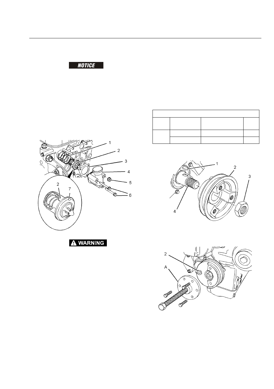
20. Install spring (1) and water temperature regulator (2)
to the cylinder head. Ensure that jiggle pin (7) on
water temperature regulator (2) is in the vertically
upward position.
21. Install a new joint (3) to the cylinder head.
22. Position outlet connection (4) onto the cylinder
head. Install nut (5) and bolts (6) to outlet connec-
tion (4). Tighten the fasteners to a torque of 8 N·m
(71 lb in).
23. Fill the cooling system with coolant to the correct
level. Refer to Operation and Maintenance Manual,
“Cooling System Coolant - Fill” for more information.
CRANKSHAFT PULLEY - REMOVE AND INSTALL
REMOVAL PROCEDURE
Start By:
a. Remove the V-belt. Refer to Disassembly and
Assembly, “V Belts Remove and Install” for more
information.
24. Loosen nut (3).
NOTE: Do not remove the nut at this time.
25. Install Tooling (A) to crankshaft pulley (2). Use Tool-
ing (A) in order to remove crankshaft pulley (2) from
crankshaft (4). Remove Tooling (A).
26. Remove nut (3).
Required Tools
Tool
Part
Number
Part Description
Qty
A
21825619
Puller
1
-
Bolt
3