JLG X23J - X700AJ Service Manual User Manual
Page 365
SECTION 3 - CHASSIS & TURNTABLE
3-338
– JLG Lift –
3121448
in two positions. Ensure that the fuel transfer pump
is oriented in the correct position.
2. Install a new O-ring seal (3) to fuel transfer pump (1).
3. Lubricate the operating plunger of fuel transfer
pump (1) with clean engine oil.
4. Position fuel transfer pump (1) on the cylinder block.
Ensure that the operating plunger is positioned cor-
rectly on the camshaft lobe. Install bolts (4). Tighten
the bolts to a torque of 6 N·m (53 lb in).
5. Connect the hoses (not shown) to fuel transfer
pump (1). Tighten the hose clamps.
NOTE: The inlet for the fuel transfer pump can be rotated
360 degrees by loosening bolt (2). The fuel inlet is
adjustable in 15 degree increments. If adjustment is
made to the position of the fuel inlet, tighten bolt (2)
to a torque of 2.5 N·m (22 lb in).
6. Turn the fuel supply to the ON position.
7. Prime the fuel system. Refer to Systems Operation,
Testing and Adjusting, “Fuel System - Prime” for
additional information.
FUEL TRANSFER PUMP - REMOVE AND INSTALL
(ELECTRICAL FUEL TRANSFER PUMP)
REMOVAL PROCEDURE
CARE MUST BE TAKEN TO ENSURE THAT FLUIDS ARE CON-
TAINED DURING PERFORMANCE OF INSPECTION, MAINTE-
NANCE, TESTING, ADJUSTING AND REPAIR OF THE PRODUCT.
BE PREPARED TO COLLECT THE FLUID WITH SUITABLE CON-
TAINERS BEFORE OPENING ANY COMPARTMENT OR DISASSEM-
BLING ANY COMPONENT CONTAINING FLUIDS. DISPOSE OF ALL
FLUIDS ACCORDING TO LOCAL REGULATIONS AND MANDATES.
KEEP ALL PARTS CLEAN FROM CONTAMINANTS. CONTAMI-
NANTS MAY CAUSE RAPID WEAR AND SHORTENED COMPONENT
LIFE.
NOTE: Put identification marks on all hoses, on all hose
assemblies, on wires and on all tube assemblies for
installation purposes. Plug all hose assemblies and
tube assemblies. This helps to prevent fluid loss and
this helps to keep contaminants from entering the
system.
1. Turn the fuel supply to the OFF position.
2. Turn the battery disconnect switch to the OFF posi-
tion.
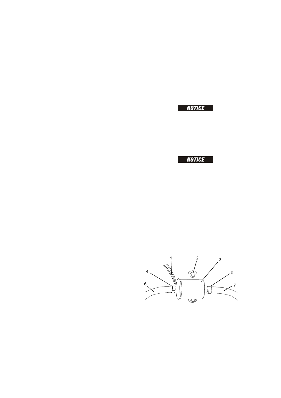
3. Disconnect harness assembly (1).
4. Loosen hose clamps (4) and (5). Disconnect hoses
(6) and (7).
5. Remove bolts (2) and remove electric transfer pump
(3).