JLG X23J - X700AJ Service Manual User Manual
Page 218
SECTION 3 - CHASSIS & TURNTABLE
3121448
– JLG Lift –
3-191
WIRING DIAGRAMSHOW TO READ A WIRING
DIAGRAM & RELATED INFORMATION
The wiring diagram, connector general layout drawing,
connector drawings, and the symbols used in trouble-
shooting are explained in this section.
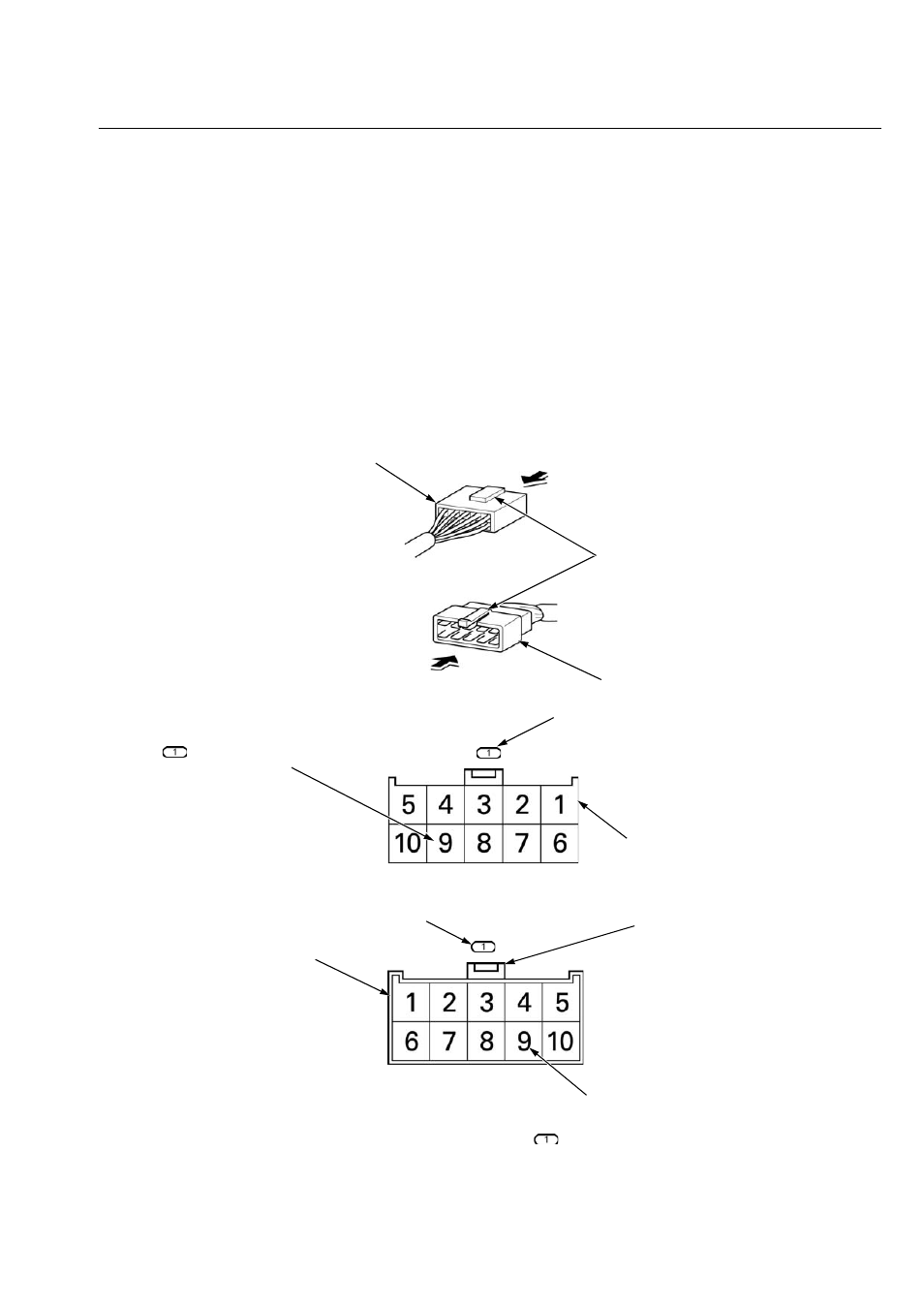
HOW TO READ CONNECTOR DRAWINGS
Connector drawings show the terminal arrangement, ter-
minal No., number of pins, and the shape of terminal
(male or female).
Both the male and female connectors are shown for the
common connectors, while only the main wire harness
side connectors are shown for the dedicated connec-
tors.The double frame connectors represent the male
connectors and the single frame connectors represent the
female connectors.
Both the male and female connectors are shown by view-
ing them from the terminal side.
FEMALE CONNECTOR
MALE CONNECTOR
LOCK
VIEWING DIRECTION
VIEWING DIRECTION
FEMALE CONNECTOR DRAWING
(SINGLE FRAME)
Female connector viewed from the
terminal side.
CONNECTOR No.
MALE CONNECTOR DRAWING
(DOUBLE FRAME)
Male connector viewed from the
terminal side.
TERMINAL No.
The system drawing shows the No.9 terminal of the
connector.
LOCK
CONNECTOR No.
TERMINAL ARRANGEMENT
The connector drawing shows the terminal arrangement of
the
connector with the lock of the connector toward up.