JLG X23J - X700AJ Service Manual User Manual
Page 139
SECTION 3 - CHASSIS & TURNTABLE
3-112
– JLG Lift –
3121448
Permissible deformation of the mounting structure,
under maximum load for series WD-H slew drives
IMPORTANT
AXIAL DEFLECTION, TILTING, RADIAL EXTENSION
(OR RADIAL CONTRACTION) OF THE MOUNTING
STRUCTURE UNDER MAX. LOAD CAUSES DEFORMA-
TION OF THE MOUNTING STRUCTURE.
SELECTING THE MOUNTING ELEMENTS
ONLY USE MOUNTING ELEMENTS OF THE CORRECT SIZE, NUM-
BER AND QUALITY. DO NOT REUSE BOLTS, NUTS, AND WASH-
ERS. USING UNSUITABLE MOUNTING ELEMENTS MAY CAUSE
THE BOLTED UNION TO FAIL AND THUS THE ENTIRE CONSTRUC-
TION TO FAIL.
Figure 3-191. Do not use continuous thread
The function and service life, as well as the durability of
the bolted union are highly dependent on grip ratio, the
type of bolt, and the dimensions of the bolts. Conse-
quently select the mounting elements on the basis of the
following:
• Do not use any bolts with a fully threaded shaft.
• Only use new, quality class 10.9 (metric) bolts or SAE
Grade 8.
• Maintain the grip ratio (grip length to the diameter of
the bolt) of at least
≥
5 to maximum
≤
10.
• Select bolt length to ensure that the minimum insertion
depth is reached.
• If the permissible interfacial pressure is exceeded use
appropriate washers.
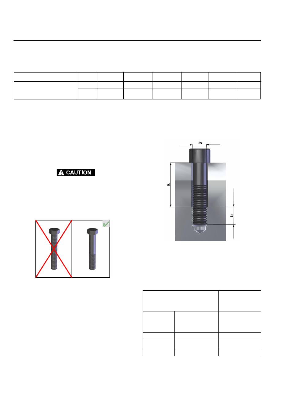
Figure 3-192. Mounting element
Minimum insertion depth depending on fracture
strength of the mounting structure
Size of the slew drive
≥
146
≥
220
≥
300
≥
373
≥
490
≥
625
Permissible deformation of the
mounting structure per support sur-
face
[mm]
0.10
0.11
0.12
0.13
0.15
0.16
[in]
0.0040
0.0044
0.0048
0.0052
0.0059
0.0063
Fracture strength Rm of the
mounting structure
Minimum
insertion depth
(le)
in N/mm²
in lbf/in²
Strength class
10.9 / Grade 8
500 to 700
72520 to 101525
le = 1.4*ds
700 to 900
101525 to 130535
le = 1.1*ds
over 900
over 130535
le = 0.9*ds