JLG X23J - X700AJ Service Manual User Manual
Page 143
SECTION 3 - CHASSIS & TURNTABLE
3-116
– JLG Lift –
3121448
1)
F
M
for hydraulic bolt-tensioning cylinder pretension ed
to 85% of yield strength.
Table 3-8.
1)
F
M
for hydraulic bolt-tensioning cylinder pretensioned
to 85% of yield strength.
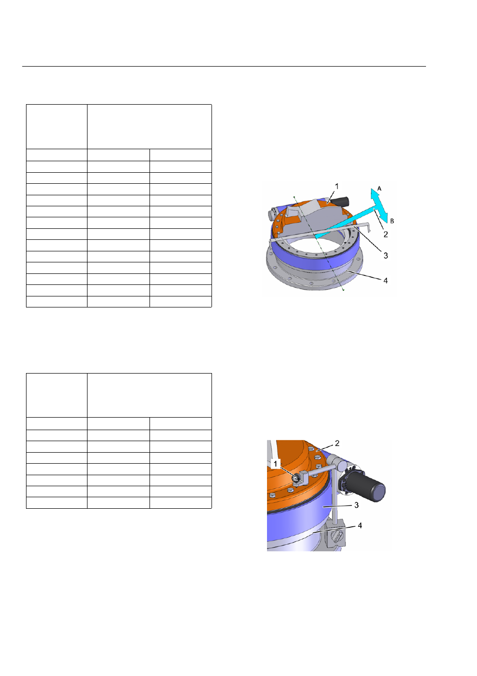
DETERMINING THE TILTING CLEARANCE
Tilting clearance increases as raceway system wear
increases. To determine the increase in tilting clearance a
basic measurement must be executed in installed status
and prior to first-time operation. This is the only way to
determine changes.
Figure 3-195. Determine tilting clearance
1. Upper mounting structure
2. Tilting direction
3. Main load-carrying zone
4. Lower mounting structure
Figure 3-196. Measurement setup
5. Dial gauge
6. Upper mounting structure
Table 3-7.
Mounting
bolt dimen-
sions
Mounting pretension force
F
M
1)
Strength class 10.9 in
kN
lbs
M24
282
63396
M27
367
82505
M30
448
100714
M33
554
124544
M36
653
146800
M42
896
201429
M45
1043
234476
M48
1177
264600
M52
1405
315857
M56
1622
364640
M60
1887
424215
M64
2138
480642
M68
2441
548759
Mounting
bolt dimen-
sions
Mounting pretension force
F
M
1)
Strength class 10.9 in
kN
lbs
1 – 8 UNC
301
67668
1 1/8 – 7 UNC
379
85203
1 1/4 – 7 UNC
481
108133
1 3/8 – 6 UNC
573
128816
1 1/2 – 6 UNC
697
156692
1 5/8 – 6 UNC
832
187041
1 3/4 – 5 UNC
942
211770