JLG X23J - X700AJ Service Manual User Manual
Page 69
SECTION 3 - CHASSIS & TURNTABLE
3-42
– JLG Lift –
3121448
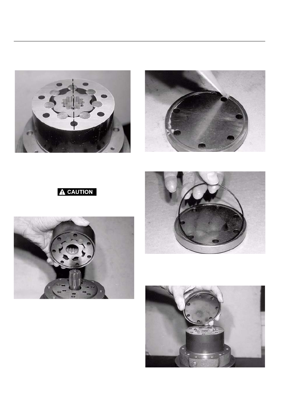
THE MOST INSIDE TWO ROLLS (CALLED “MINIMUM VOLUME
CHAMBER”).
Figure 3-106.
23. Place the roller gerotor (40) on the cardan shaft with
theO-ring seal (38) faced down towards the distribu-
tor plate.
THE ROLLER GEROTOR (40) MUST BE ASSEMBLED WITH THEMI-
NIMUM VOLUME CHAMBER ON THE MOTOR AXIS OF SYMME-
TRY, OIL PORT SIDE (SAME AS FOR TIMING SHAFT).
Figure 3-107.
24. Apply a slight coat of grease on the O-ring seat of
the motor cover (41).
Figure 3-108.
25. Place the O-ring seal (38) into its seat.
Figure 3-109.
26. Place the motor cover (41) with the O-ring seal (38)
faced down towards the roller gerotor and the screw
holes lined up.
Figure 3-110.
This manual is related to the following products: