TOHO ELECTRONICS TTM200 User Manual
Page 39
48-7009-E
3-17
3)
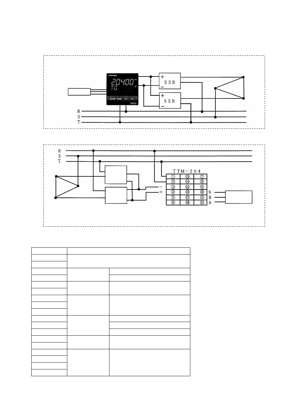
Input: resistance temperature detector, output 1: SSR drive voltage and 3-phase 200 V
Temperature sensor
(resistance temperature
detector)
(Example) TTM-204
* Usable SSR in 3-pahse 200 V is a product
with the input current of 10 mA or less.
Heater
★ Connection configuration
★ Configuration example
Heater
* Take care when wiring,
as SSR has polarity of
“+” and “-.”
* Take care wiring, as “A,” “B”
and “b” are designated on a
resistance temperature detector.
Power
supply
Resistance
temperature
detector
-
SSR
+
-
SSR
+
Power
supply
Terminal description for the above wiring example
Terminal No.
Description
①
Power supply
②
③
Output 1
“-” side
④
“+” side
⑤
Output 2
Not used in this case.
⑥
⑦
Output 3
Output 4
Not used in this case.
⑧
⑨
⑩
Input
b
⑪
B
⑫
A
⑬
Communication
Not used in this case.
⑭
⑮
CT or DI input
Not used in this case.
⑯
⑰
⑱
* SSR may be shorted out
due to its internal failure.
The use of “temperature
fuses” or an
“over-temperature
prevention device” is
recommended to cut off the
output circuit of SSR.