Magnified drawing – TOHO ELECTRONICS TTM200 User Manual
Page 231
48-7009-E
6-83
■
Zone Threshold Switching Sensitivity Range Setting
SEt23
ZbNK
Setting Contents
Initial
Value
4
ASC
Zone Threshold Switching Sensitivity Range Setting 3
2
During Temperature Input
0~999(0.0~999.9)
(℃)
During Analog Input
0~9999
(
digit)
※
Sets the sensitivity setting for the threshold of
the bank auto-switching.
At bAF=0(OFF) and bAS=*0 or *1, there will
be nol indication when the SET02 LR=0.
※
When SET04 bANKH=0, the setting becomes
invalid.
There will be no indications either.
※4
Zone Threshold Switching Sensitivity Range Setting (ASC)
Sets the Sensitivity Range to each intermediate points to which the bank auto-switching is done.
Setting Range: During the Temperature Input 0~999(0.0~999.9)
(℃)
During the Analog Input 0~9999
(
digits)
NOTE: With Threshold (PM 1 to PM 7), it will be common value.
NOTE: It will be ±(ASC/2) with (PM1 to PM7) as the center.
As for the behavior, please refer to the “Zone Threshold Switching Sensitivity Range Setting
Behavior Diagram” below.
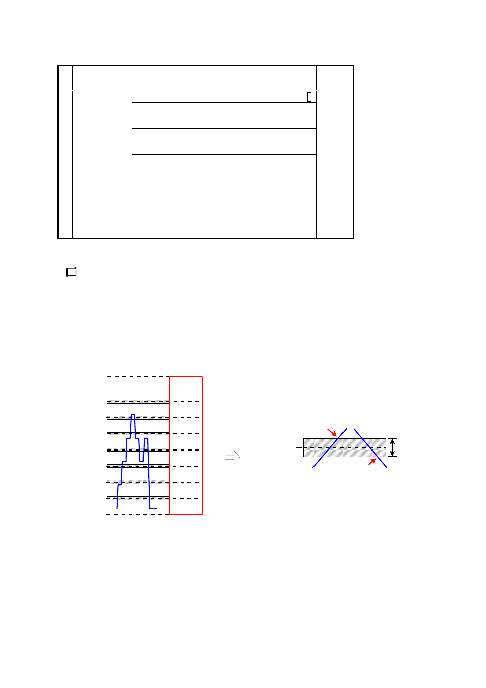
■
Zone Threshold Switching Sensitivity Range Setting Behavior Diagram
With each PM*Value as the center, the value set by ASC shall be the sensitivity range.
Auto-Switching
Source
BANK0
BANK1
BANK2
BANK3
BANK4
BANK5
BANK6
BANK7
PM1
PM2
PM3
PM4
PM5
PM6
PM7
SLH
SLL
PM*
(*=1~7)
Magnified
Drawing
ASC
When
"increasing"
Auto-Switching
Source
When
"decreasing"
Outset of
BANK
switching
Outset of
BANK
switching
Auto-Switching
Source
NOTE: This setting is effective only when the Bank Automatic Switching Source Setting (bAS) is selected
either Remote SV or PV.
<
Conditions when ASC can be set>
When (bAS = 2)
When SET02 (LR = 1, 2) at (bAS = 0)
<
Conditions when ASC cannot be set>
When (bAS = 1)
(bAS = 0) but when SET02 (LR = 0).