TOHO ELECTRONICS TTM200 User Manual
Page 127
48-7009-E
5-57
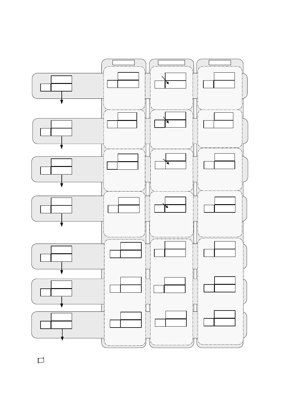
■ Regarding operation and display of a program run
The diagram below shows “screen display during a program run.” The screens are categorized into
“before run,” “run in process” and “run end” depending on run status.
22
PROG
%0
89
89
%0
0
0
30
0
0
29
(0
0
0
00
0
0
30
(1
0
0
00
0
0
30
(2
0
0
00
0
0
30
(3
22
PROG
%
22
0
0
29
(1
22
END
%E
PROG
STOP
0
PROG
STOP
PROG
RUN
1
PROG
END
E
%1
89
89
0
0 30
0
0
29
(1
0
0
50
0
0
30
(1
0
0
30
0
0
20
(2
0
0
10
0
0
03
(3
%E
89
23
%
89
----
- --
0
0 00
0
0
00
E
0
0
50
0
0
30
(1
0
0
50
0
0
30
(1
0
0
0
30
0
0
20
(2
0
0
30
0
0
20
(2
0
0
10
0
0
03
(3
0
0
10
0
0
03
(3
-
- --
-
Program run screen
PV value
PROG/remaining
time/ENd
Press MODE key
Step SV screen
PV value
Step SV value
Press MODE key
Step time monitor
Step setting time
Step remaining
time
Press MODE key
Program run/stop screen
PRoG
SToP/RUN/ENd
Press MODE key
* The timer set for use is displayed.
Unused monitors are not displayed.
Timer 1 monitor *
Timer 1 ON time
Timer 1 OFF time
Press MODE key
Timer 2 monitor *
Timer 2 ON time
Timer 2 OFF time
Press MODE key
Timer 3 monitor *
Timer 3 ON time
Timer 3 OFF time
Press MODE key
Returns to the run mode display
screen.
Before run
Key operation: ①
PV display: PV value
SV display: PRoG
Auxiliary display: Blank (no
display)
Run in process
Run end
Key operation: ②
PV display: PV value
SV display: ----
Auxiliary display: Blank (no
display)
C (no display of analog time)
Key operation: ⑤
PV display: --:--
SV display: --:--
Auxiliary display: Blank (no
display)
Key operation: ⑧
PV display: PRoG
SV display: StoP
Auxiliary display: Blank (no
display)
Key operation: ⑪
PV display: ON time setting
value
SV display: OFF time
setting value
Auxiliary display: Timer No.
Key operation: ⑬
PV display: ON time setting
value
SV display: OFF time
setting value
Auxiliary display: Timer No.
Key operation: ⑮
PV display: ON time setting
value
SV display: OFF time
setting value
Auxiliary display: Timer No.
Key operation: ①
PV display: PV value
SV display: Remaining time
Auxiliary display: Current
step No.
TIME blinking
Key operation: ③
PV display: PV value
SV display: Step SV value
Auxiliary display: Current
step No.
C (no display of analog time)
Key operation: ⑥
PV display: Step setting
time
SV display: Remaining time
Auxiliary display: Current
step No.
TIME blinking
Key operation: ⑨
PV display: PRoG
SV display: RUN
Auxiliary display: Current
step No.
Key operation: ⑫
PV display: ON time
remaining time
SV display: OFF time
remaining time
Auxiliary display: Timer No.
Key operation: ⑭
PV display: ON time
remaining time
SV display: OFF time
remaining time
Auxiliary display: Timer No.
Key operation: ⑯
PV display: ON time
remaining time
SV display: OFF time
remaining time
Auxiliary display: Timer No.
Blinks
during a
pause.
Blinks
during a
pause.
Blinks
during a
pause.
Blinks
during a
pause.
Key operation: ①
PV display: PV value
SV display: ENd
Auxiliary display:
“E”
displayed
Key operation: ④
PV display: PV value
SV display: Final step SV
value
Auxiliary display:
“E” displayed
C (no display of analog time)
Key operation: ⑦
PV display: 00:00
SV display: 00:00
Auxiliary display:
“E”
displayed
Key operation: ⑩
PV display: PRoG
SV display: ENd
Auxiliary display:
“E”
displayed
Key operation: ⑪
PV display: ON time setting
value
SV display: OFF time
setting value
Auxiliary display: Timer No.
Key operation: ⑬
PV display: ON time setting
value
SV display: OFF time
setting value
Auxiliary display: Timer No.
Key operation: ⑮
PV display: ON time setting
value
SV display: OFF time
setting value
Auxiliary display: Timer No.
The numbers of ① to ⑯ in the diagram indicate key operations. Details are shown in the “program
run mode” operation list table in the next page.