2 terminal arrangement, Terminal arrangement -3 – TOHO ELECTRONICS TTM200 User Manual
Page 25
48-7009-E
3-3
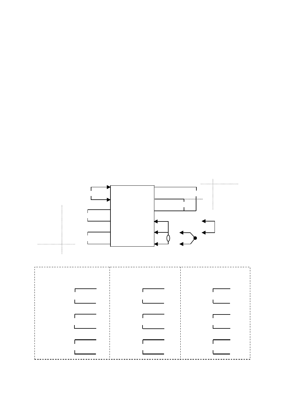
3.2 Terminal arrangement
Notation for terminal arrangement is as follows.
C:
Common
NO:
Normal open
+, -:
There is polarity for wiring.
A, B, b: There is designation for wiring.
CT:
Current transformer input (no polarity)
DI:
Digital input
RTD: Resistance temperature detector input
TC:
Thermocouple input
I:
Current input
V:
Voltage input (excluding 0 - 10 mV)
* Parameters can be used for changing input types. (Multi-input)
* “NO” and “C” for outputs are for the equipment model with relay contact output. “+” and “-” for
other than the equipment model with relay contact output.
* Terminal block is not provided in case the model selection is not made at the product model.
★ TTM-204
* Outputs 3 and 4 are for common (C) shared
Relay Open collector
① ⑬ ⑦
NO
+
Input power supply
② ⑭ ⑧
NO
+
Output 4
-
C
③ ⑮ ⑨
C
-
Output 1
+
NO
④ ⑯ ⑩
b
+
-
C
⑤ ⑰ ⑪
B
-
-
Output 2
+
NO
⑥ ⑱ ⑫
A
+
Relay
RTD input TC input Analog input
0 - 10 mV input
Output 3
Other than
relay output
A
⑬
A
⑬
A
⑬
RS-485
RS-485
RS-485
B
⑭
B
⑭
B
⑭
⑮
⑮
⑮
CT 1 input
DI 1 input
CT 1 input
⑯
⑯
⑯
⑰
⑰
⑰
CT 2 input
DI 2 input
DI 2 input
⑱
⑱
⑱
* Only the above can be selected
for the model with CT and DI.
Specifications for communication
and 2 points of CT
Specifications for communication
and 2 points of DI
Specifications for communication,
1 point of CT and 1 point of DI
Main body rear surface terminals
+
+
+
-
-
-