TOHO ELECTRONICS TTM200 User Manual
Page 114
48-7009-E
5-44
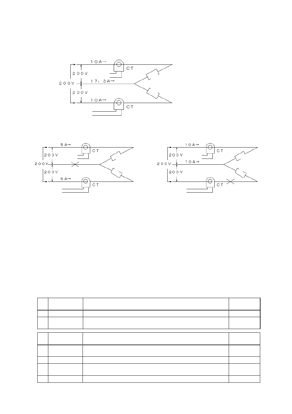
■ V connection
Example: Where 2 heaters of 200 V and 2 kW are used
[When normal]
To equipment
CT input
To equipment
CT input
Load
Load
The current that flows in the target device for CT installation is 17.3 A (≒√3 × 10 A).
[Disconnected on the common side]
To equipment
CT input
To equipment
CT input
Load
Load
[When disconnected on load side]
To equipment
CT input
To equipment
CT input
Load
Load
Disconnected
Disconnected
Current when disconnected = 10A
(1/2)
= 5A
Current when disconnected = 10A
1
= 10A
The heater disconnection detection current value when disconnection occurs on the common side is as
follows.
Heater disconnection detection current value = (17.3 +5)/2 ≒ 11.2 [A]
The heater disconnection detection current value when disconnection occurs on the load side is as
follows.
Heater disconnection detection current value = (17.3 +10)/2 ≒ 13.7 [A]
Hence, the heater disconnection detection current value is to be 13.7 A in order to detect disconnection
in both cases.
■ Example of parameter setting
The following is an example when CT 1 and 2 are installed on the outputs 1 and 2 respectively in the
connection shown above and CT abnormality is provided as output on the output 3.
SEt6
oUt2
Name
Setting content
Setting value
o3F
Target connection setting
Event output
2
E3F3
Event function 3 setting (CT
abnormality)
All modes, no added function, CT 1
abnormality + CT 2 abnormality
003
SEt12
CT
Name
Setting content
Setting value
CI1
CT 1 target connection setting
Connected to OUT 1 (allowed to be
set in case of DO)
1
Ct1
CT 1 abnormal current value setting
13.7
CI2
CT 2 target connection setting
Connected to OUT 2 (allowed to be
set in case of DO)
2
Ct2
CT 2 abnormal current value setting
13.7