3 wiring to each terminal, Wiring to each terminal -7 – TOHO ELECTRONICS TTM200 User Manual
Page 29
48-7009-E
3-7
3.3 Wiring to each terminal
In connection diagrams, left side of the terminal number represents inside the equipment while right side
shows the external side of the equipment.
★ Power supply
TTM-204
Terminal Nos. ① and ②
TTM-205
TTM-207
TTM-209
TTM-204
Type of power supply
Fluctuation range
Frequency
Power consumption
100 to 240 VAC
85 to 264 VAC
50/60 Hz
10 VA or less
24 VAC
21.6 to 26.4 VAC
50/60 Hz
4 W or less
24 VDC
21.6 to 26.4 VDC
4 W or less
TTM-205/207/209
Type of power supply
Fluctuation range
Frequency
Power consumption
100 to 240 VAC
85 to 264 VAC
50/60 Hz
11 VA or less
24 VAC
21.6 to 26.4 VAC
50/60 Hz
6 W or less
24 VDC
21.6 to 26.4 VDC
6 W or less
* Wire the power supply for instruments in such a way that they don’t receive noise from the power supply of the
power devices.
The use of a noise filter is recommended in case that the equipment is vulnerable to noises.
Take care the following when a noise filter is used.
◎
Install the noise filter as close to a temperature controller as possible.
Wire the instruments in as short a distance as possible to output lines (secondary side) of the noise filter and
power terminals for the temperature controller.
◎
Isolate the noise filter input line (primary side) from its output line (secondary side).
High-frequency elements of noises may be induced, resulting in no provision of much noise attenuation effect as
expected, in case of input and output wires being close one another, such as being bundled together or installed in
a same duct or tube.
◎
Wire the grounding wire of the noise filter in as short a distance as possible.
A long grounding wire is equivalent to insert of an inductance, resulting in deteriorated high-frequency
characteristics.
◎
Before installing the noise filter, peel off the paint applied on a mounting plate of the noise filter as appropriate, in
order to reduce the contact resistance between the noise filter and equipment housing.
* For the power supply, use and twist wires that has lesser voltage drop.
* It takes about 4 seconds for the unit to activate after its power is turned on. Use delay relays when
using the equipment for generating signals for interlocking circuits.
* In case of using the equipment with a 24 V power supply, supply the power from a SELV circuit
(power supply secured with safety).
* The equipment is not supplied with power supply switch fuses. Separately install fuses in proximity
of the equipment, as needed.
◎ Recommended fuse rating: Rated voltage of 250 V and rated current of 1A
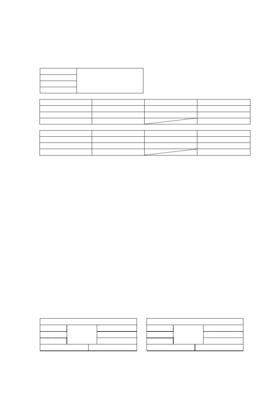
* The input power supply and the input/output are isolated one anther on the equipment.
* Isolation diagram
Where relays and open collectors are included in
outputs
Where outputs are SSRs, current outputs or voltage
outputs
Power supply circuit
Power supply circuit
PV input
CPU circuit
Output 1
PV input
CPU circuit
Output 1
AI input
Output 2
AI input
Output 2
CT input
Outputs 3 to 7
CT input
Outputs 3 to 7
DI
Communication
DI
Communication
* No. of outputs depends on specifications and models.
Isolated
* Outputs 3 to 7 are isolated.
------ Non-isolated