5 explanation of the program run function, Explanation of the program run function -47 – TOHO ELECTRONICS TTM200 User Manual
Page 117
48-7009-E
5-47
5.5 Explanation of the program run function
■ The digital controller TTM-200 Series can provide a simple program controller. This chapter
explains the program run of TTM-200 Series.
• A program run of this product is established by automatically controlling “bank function” and
“program step function.” The process flow for establishing a program run is described below.
■ Program run operation explanation diagram
STEP1
STEP2
STEP3
STEP4
STEP5
STEP6
STEP7
STEP8
SV1
50℃
TIM1
00:30
ST1BK
BANK1
BANK1
RMP
10
P1
4.0
・
・
・
o2F
I
20
D
5
SV2
100℃
TIM2
00:40
ST2BK
BANK1
BANK1
RMP
10
・
・
・
o2F
SV3
150℃
TIM3
00:50
ST3BK
BANK1
BANK1
RMP
10
・
・
・
o2F
SV4
200℃
TIM4
01:00
ST4BK
BANK1
BANK1
RMP
10
・
・
・
o2F
SV5
150℃
TIM5
00:30
ST5BK
BANK2
BANK2
RMP
5
・
・
・
o2F
TIMER ON
DELAY
SV6
100℃
TIM6
00:40
ST6BK
BANK2
BANK2
RMP
5
・
・
・
SV7
150℃
TIM7
00:50
ST7BK
BANK1
BANK1
RMP
10
・
・
・
o2F
SV8
20℃
TIM8
00:10
ST8BK
BANK3
BANK3
RMP
30
・
・
・
o2F
RUN OUT
BANK0
RMP
P1
3.0
M
AX
.
1
6
P
AR
AM
E
T
E
R
・
・
・
o2F
END OUT
I
0
D
0
BANK0
RMP
・
・
・
o2F
END OUT
START
OPERATION
END
OPERATION
END
PV
BANK0
RMP
M
AX
1
6
パ
ラメ
ー
タ
・
・
・
o2F
END OUT
OPERATION
STOP
STOP
OPERATION
STOP OPERATION
P1
2.0
I
10
D
2
P1
3.0
I
0
D
0
P1
3.0
I
0
D
0
P1
4.0
I
20
D
5
P1
4.0
I
20
D
5
P1
4.0
I
20
D
5
P1
4.0
I
20
D
5
P1
2.0
I
10
D
2
P1
2.0
I
10
D
2
SET22
SETTING
VALUE
MAX. 8 STEPS
SET20
SETTING
VALUE
STEP SV SETTING
STEP TIME SETTING
STEP BANK SETTING
o2F
TEMP. CHANGE PATTERN
REFER
1BANK
OPERATION
STOP
OUTPUT EXAMPLE
TIMER ON
DELAY
o2F
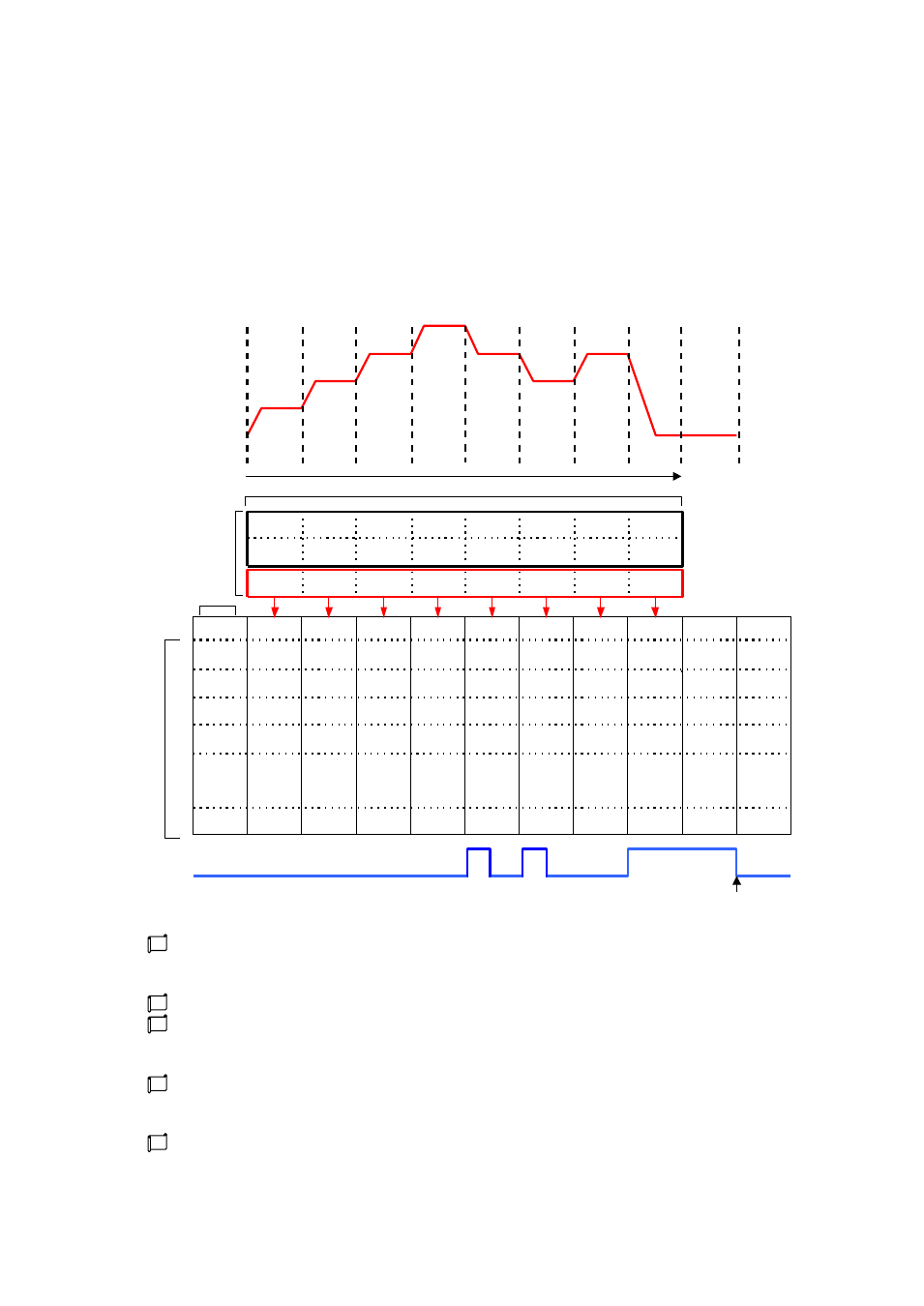
A certain pattern of a status to be changed, such as temperature, is developed. The diagram
above shows an example of a temperature change pattern. To automatically change this pattern,
it is divided into the smallest units referred to as STEP.
Set the auto run sequence of a STEP to the SET 22 “program step” parameter.
For “step bank setting” of SET 22, SET 20 “bank function” is referred. With this reference,
operations of “input, output, timer output, event input/output, control parameters, etc.” for each
step are determined.
Parameters necessary for such control as “input,” “output,” “timer output,” or “event” are set.
The steps during an auto run sequence are automatically switched by the sequence, and banks set
with control parameters are also switched. This mechanism provides a program run.
This product allows a program run in eight steps at most.
o2F OUTPUT EXAMPLE
MAX.
1
6
P
AR
AME
T
ER