TOHO ELECTRONICS TTM200 User Manual
Page 36
48-7009-E
3-14
TTM-205/209
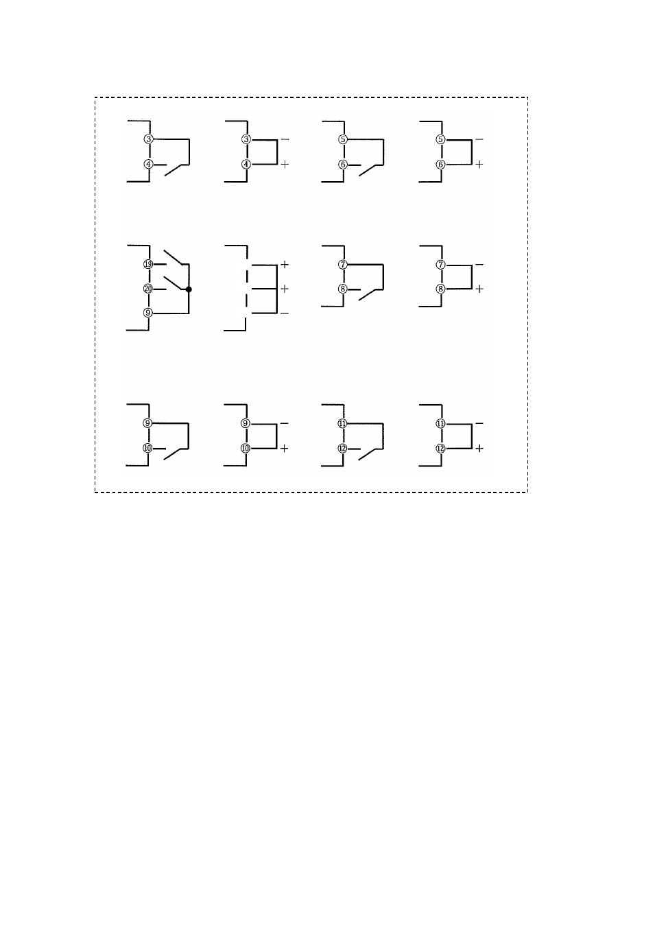
Output 1
Output 2
Outputs 3 and 4
Output 5
Relay
Output 6
SSR/current/voltage/
open collector
Relay
SSR/current/voltage/
open collector
Relay
Open collector
Relay
Open collector
* Outputs 3 and 4 are for common shared
Relay
Open collector
Output 7
Relay
Open collector
○
19
○
20
○
21
* Max. 7 points of outputs are provided. They are usable for control output, event output, RUN/RDY
output, transmission output, and timer outputs (3 points).
They should be designated at order placement. See the model table on page 1-3.
* No. of outputs selectable depends on models. In the table “★ Output” on page 3-12, cells filled
with diagonal lines indicate that none is selectable. Selection can also be checked on the model table
on page 1-3.
* “NO” and “C” for outputs are for the equipment model of relay contact output. “+” and “-” for
outputs are for other than the equipment model of relay contact output. Properly wire outputs to
target connections, as target connections are designated.
(Take sufficient care the polarity “+” and “-” when wiring.)