TOHO ELECTRONICS TTM200 User Manual
Page 155
48-7009-E
6-7
■ PV filter setting
SEt01
INP1
Setting content
Initial value
11
PdF1
0.0 to 99.9 (seconds)
0.0
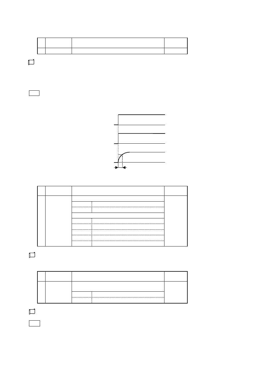
The PV filter setting is a function that demonstrates the CR filter effect on software through performing a first-order lag calculation for
PV of the input 1.
The filter effect is set using the time constant [t].
(Time constant is defined as the time required for PV to reach about 63 % when an input changes in a step configuration.)
* CR filter --- a filter of first-order lag
Note Application of PV filter
(1) Effect of noise is alleviated due to elimination of high-frequency noise when electric noise applies on inputs.
(2) Response can be delayed against abrupt change of an input.
100%
0%
Time
100%
0%
Time
100%
0%
Time
63%
Time constant (t)
■ Input signal
■ Input read in
When no digital PV filter exists
[Time constant (t) = 0]
When a digital PV filter exists
[Time constant (t) > 0]
■ Decimal point position setting
SEt01
INP1
Setting content
Initial value
12
dP1
Thermocouple/resistance temperature detector input
0
0
Unit of 1°C
0.0
Unit of 0.1
C
Current/voltage input
0
1/digit
0.0
0.1/digit
0.00
0.01/digit
0.000
0.001/digit
0.0000
0.0001/digit
A decimal point position is set for PV of the input 1.
■ °C/°F switchover
SEt01
INP1
Setting content
Initial value
13
C/F1
Press the MODE key for making a setting effective (including
reverse feed).
°C
°C
Celsius
°F
Fahrenheit
Set the unit of temperature input.
Note Switchover of °C/°F may result in change of each setting value due to limits being applied, such as SLH, SLL, tRH and
tRL.