Alarm displays – Watlow CLS200 User Manual
Page 74
Chapter 3: Using the CLS200
CLS200 Series User’s Guide
58
Watlow Anafaze
Doc.# 0600-3050-2000
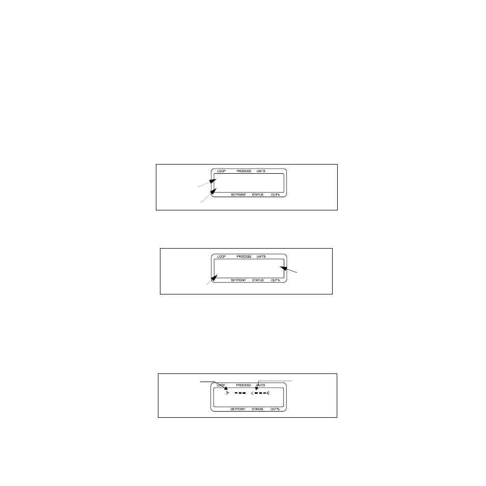
Alarm Displays
If a process, deviation, failed or system sensor alarm oc-
curs, the controller switches from any Single Loop display
or Bar Graph display to the Single Loop display for the loop
with the alarm. The global alarm output turns on and a
two-character alarm code appears in the lower left corner
of the Single Loop display. If the alarm is for a failed sen-
sor, a short message appears in place of the process vari-
able and units. Control outputs associated with failed
sensors are set to the value of the SENSOR FAIL HT/CL
OUTPUT % parameter (default, 0%). The alarm code blinks
and displays cannot be changed until the alarm has been
acknowledged. Once the alarm is acknowledged, the alarm
code stops blinking. When the condition that caused the
alarm is corrected, the alarm messages disappear.
Figure 3.6 Single Loop Display with a Process
Alarm
Figure 3.7 Failed Sensor Alarm in the Single
Loop Display
Alarms that still exist but have been acknowledged are dis-
played on the Bar Graph display. A letter or symbol indi-
cates the alarm condition. See Table 3.3 on page 59 for a
full list of alarm codes, failed sensor messages and alarm
symbols.
Figure 3.8 Alarm Symbols in the Bar Graph
Display
ALARM
Alarm Code
Loop Number
180
°F
180AUTO
02
LP
ALARM
Failed Sensor
Alarm Code
Description
03 T/C BREAK
FS 25MAN 0
ALARM
01 F
08
AAAA
MAMA
Open
Low Process
or Low Deviation
on Loop 5
on Loop 1
Thermocouple