Scaling and calibration, Configuring dual dac outputs – Watlow CLS200 User Manual
Page 202
Chapter 9: Troubleshooting and Reconfiguring
CLS200 Series User’s Guide
186
Watlow Anafaze
Doc.# 0600-3050-2000
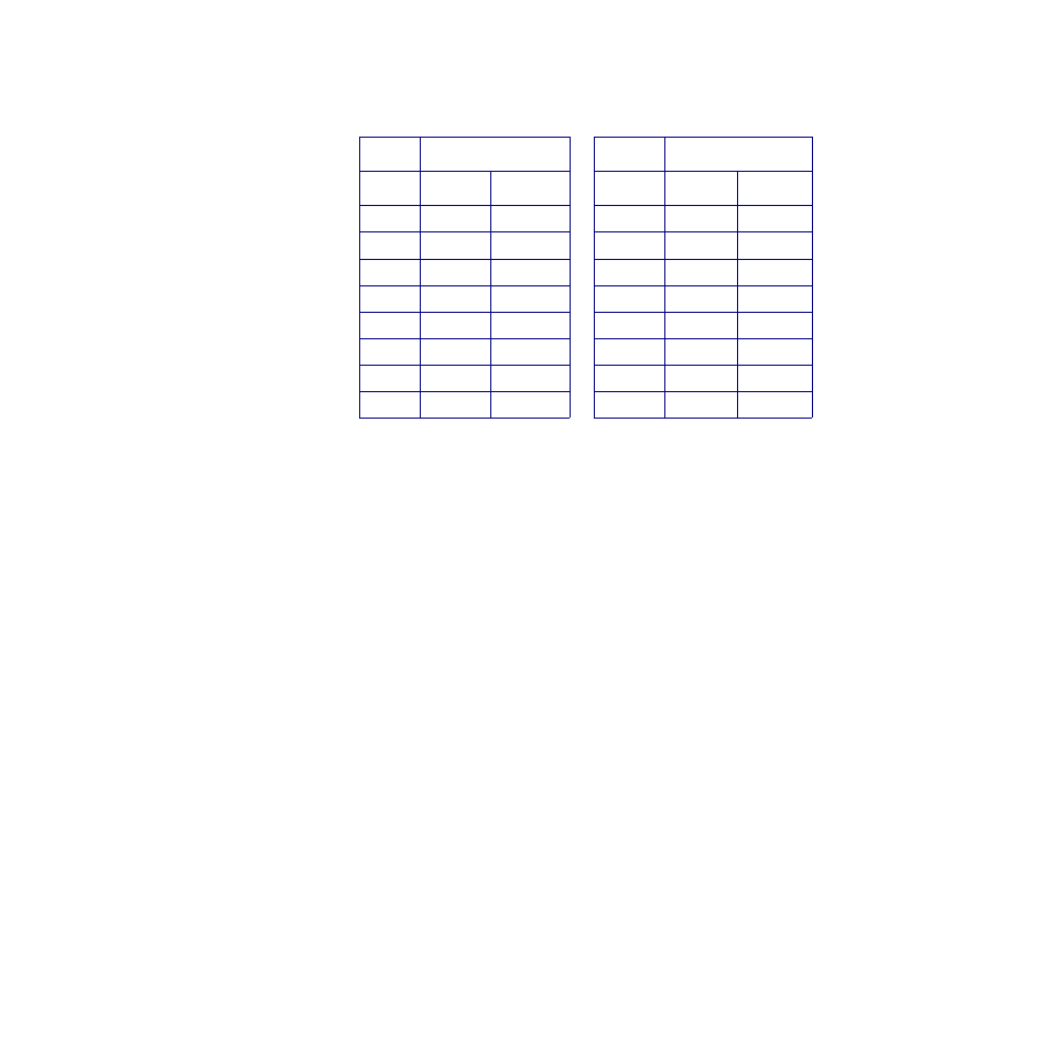
Table 9.15 Resistor Locations for CLS216
Voltage Inputs
Scaling and Calibration
The controller provides offset calibration for thermocouple,
RTD, and other fixed ranges, and offset and span (gain) cal-
ibration for linear and pulse inputs. In order to scale linear
input signals, you must:
1.
Install appropriate scaling resistors. (Contact Watlow
Anafaze’s Customer Service Department for more in-
formation about installing scaling resistors.)
2.
Select the display format. The smallest possible range
is -.9999 to +3.0000; the largest possible range is
-9,999 to 30,000.
3.
Enter the appropriate scaling values for your process.
Configuring Dual DAC Outputs
Dual DAC modules ship with both outputs configured for
the signal type and span ordered. The module contains two
independent circuits (DAC1 and DAC2). These circuits can
be configured for different output types. Remove the board
from the housing and set the jumpers. The odd numbered
jumpers determine the signal from DAC1; the even num-
bered jumpers determine the output from DAC2.
Resistor Locations
Resistor Locations
Loop
RC
RD
Loop
RC
RD
1
R58
R42
9
R57
R41
2
R56
R40
10
R55
R39
3
R54
R38
11
R53
R37
4
R52
R36
12
R51
R35
5
R50
R34
13
R49
R33
6
R48
R32
14
R47
R31
7
R46
R30
15
R45
R29
8
R44
R28
16
R43
R27