Mounting the tb50, Figure 2.5 mounting bracket, Figure 2.6 mounting the tb50 – Watlow CLS200 User Manual
Page 32
Chapter 2: Installation
CLS200 Series User’s Guide
16
Watlow Anafaze
Doc.# 0600-3050-2000
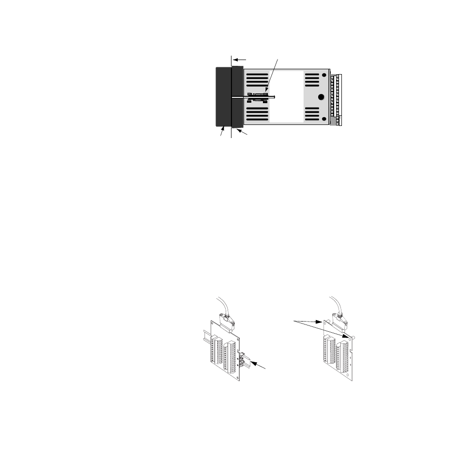
Figure 2.5 Mounting Bracket
7.
Loosen the mounting bracket screws enough to allow
for the mounting collar and panel thickness. Place
each mounting bracket into the mounting slots (head
of the screw facing the back of the processor module).
Push each bracket backward then to the side to secure
it to the processor module case.
8.
Make sure the case is seated properly. Tighten the in-
stallation screws firmly against the mounting collar to
secure the unit. Ensure that the end of the mounting
screws fit into the indentations on the mounting collar.
Mounting the TB50
There are two ways you can mount the TB50: Use the pre-
installed DIN rail mounting brackets or use the plastic
standoffs. Follow the corresponding procedures to mount
the board.
Figure 2.6 Mounting the TB50
+
2
4
6
8
10
12
14
16
18
20
22
24
26
1
3
5
7
9
11
13
15
17
19
21
23
25
Bracket (top and bottom)
Panel
Bezel
Mounting Collar
TB50
Mounted
with Standoffs
TB50
Mounted to
DIN Rail