Pulse input connections – Watlow CLS200 User Manual
Page 50
Chapter 2: Installation
CLS200 Series User’s Guide
34
Watlow Anafaze
Doc.# 0600-3050-2000
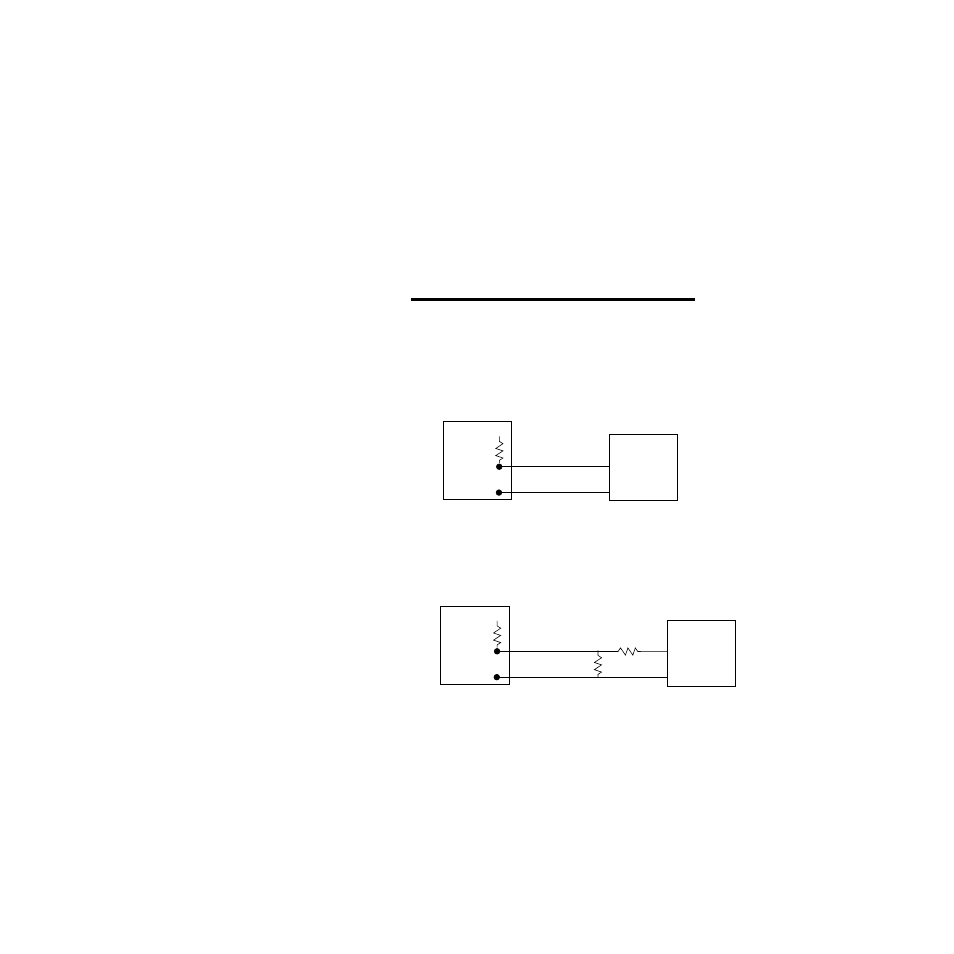
Pulse Input Connections
The CLS200 can accept a pulse input of up to 2000 Hz from
a device such as an encoder. The frequency of this input is
scaled with user-set parameters. See Setup Loop Input
Menu on page 82 and Chapter 9, Linear Scaling Examples.
This scaled value is the process variable for loop 5 on a
CLS204, loop 9 on a CLS208, or loop 17 on a CLS216.
The CLS200 can accommodate encoder signals up to 24V
Î
(dc) using a voltage divider or can power encoders with the
5V
Î
(dc) from the TB50 or TB18. The following figures il-
lustrate connecting encoders. A pull-up resistor in the
CLS200 allows open collector inputs to be used.
NOTE!
If the signal on the pulse input exceeds
10kHz the controller’s operation may be dis-
rupted. Do not connect the pulse input to a
signal source that may exceed 10kHz.
Figure 2.20 Encoder with 5VО
О
О
О
(dc) TTL Signal
Figure 2.21 Encoder Input with Voltage Divider
For encoders with signals greater than 5V
Î
(dc), use a volt-
age divider to drop the voltage to 5 volts at the input. Use
appropriate values for R
1
and R
2
depending on the encoder
excitation voltage. Be sure not to exceed the specific cur-
rent load on the encoder.
Pulse Input
Com
Encoder
+5V
Î
(dc)
10 k
Ω
CLS200 and TB50 or TB18
Pulse Input
Com
Encoder
+5V
Î
(dc)
10 k
Ω
R2
R1
CLS200 and TB50 or TB18