Technical description, Cls200 – Watlow CLS200 User Manual
Page 23
CLS200 Series User’s Guide
Chapter 1: System Overview
Doc.# 0600-3050-2000
Watlow Anafaze
7
Technical Description
This section contains a technical description of each compo-
nent of your CLS200 series controller.
CLS200
The CLS200 is housed in an 1/8-DIN panel mount package.
It contains the CPU, RAM with a built-in battery, EPROM,
serial communications, digital I/O, analog inputs, the
screen and touch keypad.
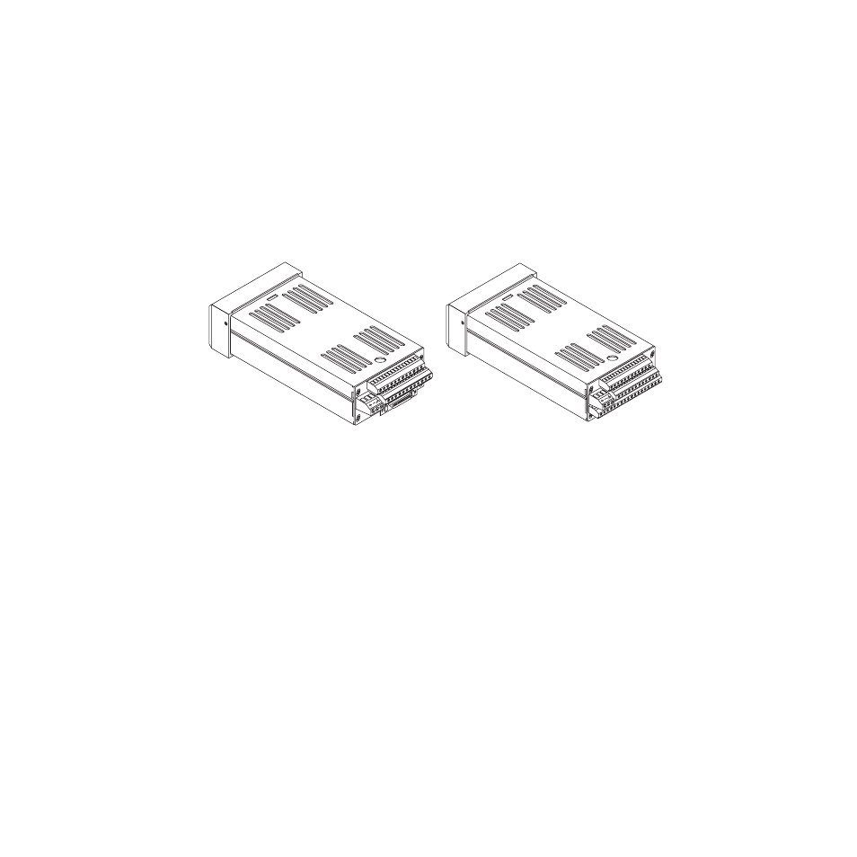
Figure 1.3 CLS200 Rear Views
The CLS200 has the following features:
•
Keypad and 2-line 16-character display.
•
Screw terminals for the power and analog inputs and
communications.
•
Input power is 12 to 24V
Î
(dc) at 1 Amp.
•
A 50-pin SCSI cable connects the digital inputs and
outputs to the 50-terminal block (TB50). The CLS204
and CLS208 are available with an 18-terminal block
(TB18) in place of the SCSI connector, as shown in Fig-
ure 1.3.
The firmware resides in an EPROM. See Replacing the
EPROM on page 176 for information on removing and re-
placing the EPROM.
The operating parameters are stored in battery-backed
RAM. If there is a power loss the operating parameters are
unchanged. The battery has a ten-year shelf life, and it is
not used when the unit is on.
The microprocessor performs all calculations for input sig-
nal linearization, PID control, alarms and communica-
tions.
CLS200 Series
with SCSI Connector
CLS204 or CLS208
with TB18 Connector