Watlow CLS200 User Manual
Page 148
Chapter 6: Enhanced Features
CLS200 Series User’s Guide
132
Watlow Anafaze
Doc.# 0600-3050-2000
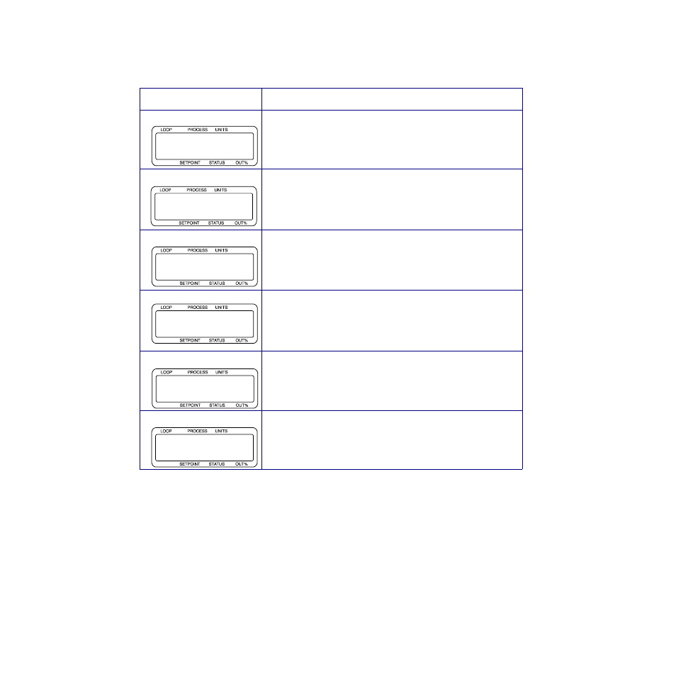
Table 6.5
Application Example: Setting Up
Differential Control
3.
Press
BACK several times until the normal loop display
appears. The setpoint of loop 2 will now be equal to
process variable of loop 1 plus 50˚ F.
4.
To complete the differential control setup, loop 1 and
loop 2 must be configured for inputs, outputs, and
alarms. See Chapter 4, Setup for information on loop
setup.
Display
User Input
Press
YES to setup the ratio control parameters for loop 2.
Assign loop 01 to be the master loop. Press
ENTER.
Enter the minimum ratio loop setpoint. For this example, we will
use 300.0° F. Press
ENTER.
Enter the maximum ratio loop setpoint. For this example, we will
use 400.0° F. Press
ENTER.
Enter the control ratio, which is the multiple applied to the master
process variable. In this example the ratio is 1.0. Press
ENTER.
Enter the setpoint differential (or offset). For this example, we have
an offset of +50. Press
ENTER.
ALARM
SETUP LOOP 02
RATIO CONTROL?
ALARM
02 RATIO CONTROL
MSTR LOOP? 01
ALARM
02 RATIO CONTROL
MIN SP? 300.0
ALARM
02 RATIO CONTROL
MAX SP? 400.0
ALARM
02 RATIO CONTROL
CTRL RATIO? 1.0
ALARM
02 RATIO CONTROL
SP DIFF.? 50