Linear scaling parameters – Watlow CLS200 User Manual
Page 102
Chapter 4: Setup
CLS200 Series User’s Guide
86
Watlow Anafaze
Doc.# 0600-3050-2000
Linear Scaling Parameters
The following parameters are only available if the input
type is LINEAR or PULSE. These parameters let you scale
the raw input readings (in millivolts or Hertz) to the engi-
neering units of the process variable.
For linear inputs, the input reading is in percent (0 to
100%) representing the 0 to 60mV input range of the con-
troller. For pulse inputs, the input reading is in Hertz (cy-
cles per second.)
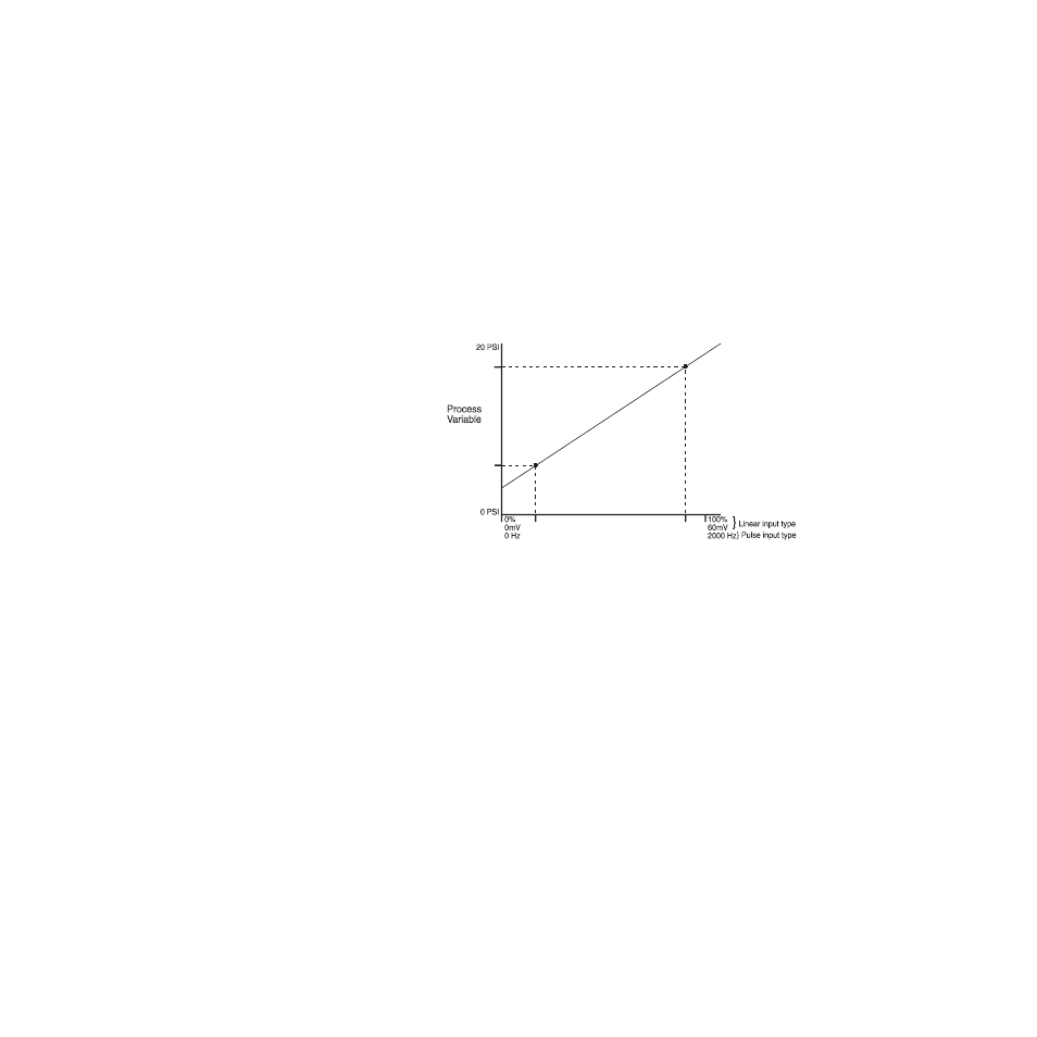
The scaling function is defined by two points on a conver-
sion line. This line relates the process variable (PV) to the
input signal. The engineering units of the process variable
can be any units—the graph in Figure 4.2 shows PSI as an
example.
Figure 4.2 Two Points Determine Process
Variable Conversion
Before you enter the values determining the two points for
the conversion line, you must choose an appropriate dis-
play format. The controller has six characters available for
process display; select the setting with the desired number
of decimal places. Use a display format that matches the
range of the process variable and resolution of the sensor.
The display format you choose is used for the process vari-
able setpoint, alarms limits, deadband, spread and propor-
tional band.
The process variable range for the scaled input is between
the process variable values that correspond to the 0% and
100% input readings. For the pulse input, it is between the
0 Hz and 2000 Hz readings. The process variable range de-
fines the limits for the setpoint and alarms. See Figure 4.3.
High Process
Variable
Low Process
Variable
Low
Reading
High
Reading
Input Reading