Cls216 input circuit, Cls216 current inputs – Watlow CLS200 User Manual
Page 200
Chapter 9: Troubleshooting and Reconfiguring
CLS200 Series User’s Guide
184
Watlow Anafaze
Doc.# 0600-3050-2000
CLS216 Input Circuit
The CLS216 can accept single-ended thermocouple, mV
Î
(dc), V
Î
(dc) and mA
Î
(dc) inputs. Unless ordered with
special inputs, the controller accepts only signals within
the standard range of -10 to 60mV
Î
(dc).
To accommodate other signals, the input circuit must be
modified. When configured for thermocouple inputs, 0
Ω
re-
sistors are installed in all RC locations. To accommodate
milliamp current signals or voltage signals outside the
standard range, resistors are added or replaced to scale the
signals to the standard range. These resistors can be in-
stalled by Watlow Anafaze or by a qualified electronics
technician using scaling resistors supplied by Watlow
Anafaze.
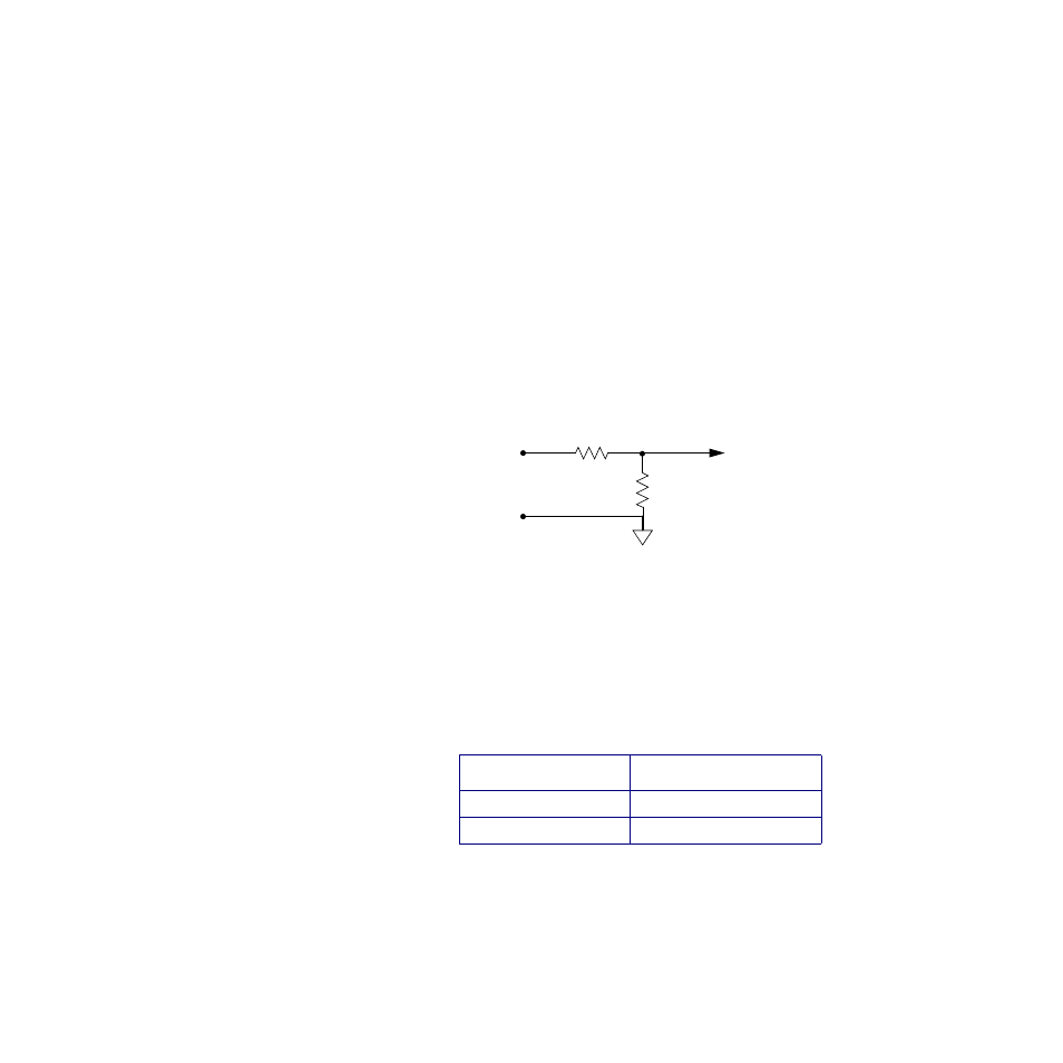
Figure 9.7 shows the schematic for one single-ended sensor
input to the CLS216. See CLS216 Current Inputs on page
184 and CLS216 Voltage Inputs on page 185 for specific in-
structions and resistor values for voltage and current in-
puts.
Figure 9.7 CLS216 Input Circuit
CLS216 Current Inputs
For each current input on a CLS216 controller, you must
install one resistor. The value of the resistor must be cor-
rect for the expected input range. Install the resistor in the
listed resistor location.
Table 9.12 Resistor Values for CLS216 Cur-
rent Inputs
Resistor tolerance:
±
0.1%
Input Range
Resistor Value RD
0 to 10 mA
6.0
Ω
0 to 20 mA
3.0
Ω
IN +
RD
Analog
Input
Terminals
RC
Com
To CLS200
Circuitry
(Voltage only)
(Voltage and Current)
Measurement