Watlow CLS200 User Manual
Page 52
Chapter 2: Installation
CLS200 Series User’s Guide
36
Watlow Anafaze
Doc.# 0600-3050-2000
Table 2.3
Digital Output States and Values
Stored in the Controller
The digital outputs sink current from the load to the con-
troller common. The load may powered by the 5V
Î
(dc)
supplied by the controller at the TB50. Alternately, an ex-
ternal power supply may be used to drive loads.
Keep in mind the following points when using an external
power supply:
•
The CLS200 power supply available from Watlow
Anafaze includes a 5V
Î
(dc) supply. When using it to
supply output loads, connect the 5V
Î
(dc) common to
the 15V
Î
(dc) common at the power supply.
•
Do not exceed +24 volts.
•
If you tie the external load to earth ground, or if you
cannot connect it as shown in (See Figure 2.22), then
use a solid-state relay.
All digital outputs are sink outputs referenced to the
CLS200 series controller common supply. These outputs
are low (pulled to common) when they are on.
The outputs conduct current when they are low or on. The
maximum current sink capability is 60 mA at 24V
Î
(dc).
They cannot “source” current to a load.
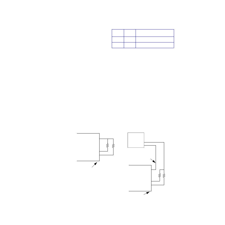
Figure 2.22 Digital Output Wiring
State Value
Description
Off
High
Open circuit
On
Low
Sinking current to common
Digital Output 1
Digital Output 2
Control Common
+5V
Î
(dc)
Loads
Digital Output 1
Digital Output 2
Using External Power Supply
Do not connect
External
Power
+
-
TB50 or TB18
Using Internal Power Supply
Loads
Supply
TB50 or TB18
to earth ground or
equipment ground