Cls204 and cls208 current inputs – Watlow CLS200 User Manual
Page 197
CLS200 Series User’s Guide
Chapter 9:Troubleshooting and Reconfiguring
Doc.# 0600-3050-2000
Watlow Anafaze
181
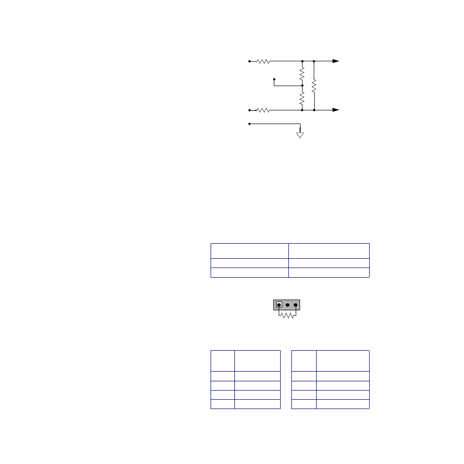
Figure 9.6 CLS204 and CLS208 Input Circuit
CLS204 and CLS208 Current Inputs
For each current input on a CLS204 or CLS208 controller
you must install a resistor. The value of the resistor must
be correct for the expected input range. Install the resistor
in the listed resistor pack (RP) location. Note the resistor
pack locations have three through holes. Install the resis-
tor as shown in the illustration below.
Table 9.6
Resistor Values for CLS204 and
CLS208 Current Inputs
Resistor tolerance:
±
0.1%
Table 9.7
Resistor Locations for CLS204 and
CLS208 Current Inputs
Input Range
Resistor Value RD
0 to 10 mA
6.0
Ω
0 to 20 mA
3.0
Ω
Loop
Resistor
Location RD
Loop
Resistor
Location RD
1
RP1
5
RP5
2
RP2
6
RP6
3
RP3
7
RP7
4
RP4
8
RP8
Com
IN-
RC (RTD)
IN+
RD
RP
Analog
Input
Terminal
Internal
RP
+5V
Î
(dc)
Reference
To CLS200
Circuitry
RC (Voltage)
+
-
RP#
RD
- 12LS Controller (111 pages)
- 8LS Controller (140 pages)
- 8PID Controller (55 pages)
- Addendum to EZwarePlus (50 pages)
- ANASCAN (62 pages)
- ANASOFT (95 pages)
- ANAWIN 2 (154 pages)
- ANAWIN 3 (23 pages)
- Calibrating Watlow Series 988 Family Process Controls (19 pages)
- CAS (98 pages)
- CAS200 (124 pages)
- CLS (180 pages)
- CLS200, MLS300 and CAS200 (92 pages)
- Control Console (12 pages)
- CPC400 (230 pages)
- DIN-A-MITE Style A (9 pages)
- DIN-A-MITE Style B (14 pages)
- DIN-A-MITE Style C (22 pages)
- DIN-A-MITE Style D (9 pages)
- DIN-Mount Adapter Instruction Sheet, Rev A (1 page)
- Dual DAC (4 pages)
- EM Gateway (28 pages)
- E-Safe Hybrid Relay Rev B (4 pages)
- E-SAFE II Hybrid Power Switch (4 pages)
- EZwarePlus Programming (264 pages)
- EZ-ZONE PM (111 pages)
- EZ-ZONE PM PID (125 pages)
- EZ-ZONE PM Express Limit (34 pages)
- EZ-ZONE PM Express (35 pages)
- EZ-ZONE PM Integrated Controller (181 pages)
- EZ-ZONE RM Limit Module Rev C (127 pages)
- EZ-ZONE RMA Modul (79 pages)
- EZ-ZONE RMC (236 pages)
- EZ-ZONE RME (124 pages)
- EZ-ZONE RMH (161 pages)
- EZ-ZONE RUI/Gateway (62 pages)
- EZ-ZONE RM-Scanner-Modul (140 pages)
- EZ-ZONE ST (97 pages)
- F4 External Event Board - Rev.B (2 pages)
- HG Series Mercury Displacement Relay (6 pages)
- LogicPro (296 pages)
- Mercury Relay or MDR Retrofit (13 pages)
- MICRODIN (106 pages)
- MICRODIN (24 pages)