Watlow CLS200 User Manual
Page 31
CLS200 Series User’s Guide
Chapter 2: Installation
Doc.# 0600-3050-2000
Watlow Anafaze
15
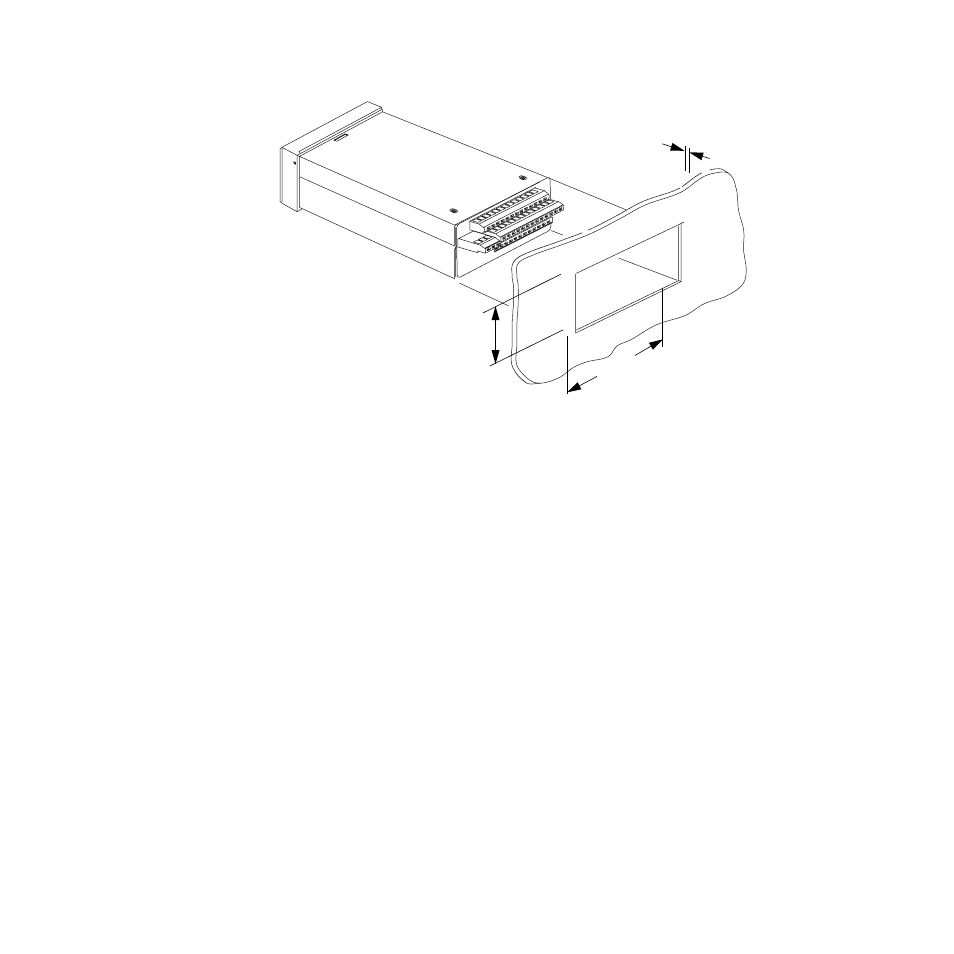
Figure 2.4 Wiring Clearances
We recommend you mount the controller in a panel not
more than 0.2 in. (5 mm) thick.
1.
Choose a panel location free from excessive heat (more
than 50° C [122° F]), dust, and unauthorized handling.
(Make sure there is adequate clearance for the mount-
ing hardware, terminal blocks, and cables. The con-
troller extends 7.40 in. (178 mm) behind the panel.
Allow for an additional 0.60 to 1.60 in. (15 to 41 mm)
beyond the connectors.)
2.
Temporarily cover any slots in the metal housing so
that dirt, metal filings, and pieces of wire do not enter
the housing and lodge in the electronics.
3.
Cut a hole in the panel 1.80 in. (46 mm) by 3.63 in. (92
mm) as shown below. (This picture is NOT a template;
it is for illustration only.) Use caution; the dimensions
given here have 0.02 in. (1 mm) tolerances.
4.
Remove the brackets and collar from the processor
module, if they are already in place.
5.
Slide the processor module into the panel cutout.
6.
Slide the mounting collar over the back of the proces-
sor module, making sure the mounting screw indenta-
tions face toward the back of the processor module.
1.80 ± 0.020 inch
(45.7 ± 0.5 mm)
Maximum Panel Thickness
0.2 inch (5 mm)
3.63 ± 0.020 inches
(92.2 ± 0.5 mm)