Thermocouple connections – Watlow CLS200 User Manual
Page 47
CLS200 Series User’s Guide
Chapter 2: Installation
Doc.# 0600-3050-2000
Watlow Anafaze
31
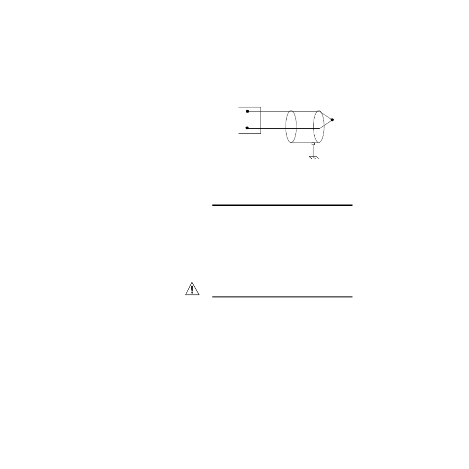
Thermocouple Connections
Connect the positive lead of any of the supported thermo-
couple types to the IN+ terminal for one of the loops and the
negative lead to the corresponding IN- terminal.
Use 18 or 20 AWG (0.5 or 0.75 mm
2
) for all the thermocou-
ple inputs. Most thermocouple wire is solid, unshielded
wire. When using shielded wire, ground one end only.
Figure 2.16 Thermocouple Connections
NOTE!
When mixing current inputs with low-voltage
inputs (thermocouples or voltage inputs <1V)
to a CLS216, connect the current signal to the
IN+ and Ref Com terminals. If no low-voltage
sensors are used, connect current inputs to
the IN+ and Com terminals on TB1. For all in-
puts to a CLS204 or CLS208, connect the
sensors to the IN+ and Com terminals.
CAUTION!
Ground loops and common mode noise can
damage the controller or disrupt measure-
ments. To minimize ground loops and com-
mon mode noise:
• With a CLS216, use only ungrounded ther-
mocouples with each thermocouple sheath
electrically connected to earth ground. The
negative sensor terminals on the CLS216 are
tied to analog common.
• With a CLS204 or CLS208, do not mix
grounded and ungrounded thermocouples. If
any thermocouple connected to the control-
ler is of grounded construction, all thermo-
couples should be of grounded construction
White
Red
CH IN+
*CH IN-
Shield (if present)
Earth Ground
at Process End
*For CLS216 use Com
Type J
thermocouple