Rear panel features, For information on connecting inputs, see the, Section on – Extron Electronics SME 100 User Guide User Manual
Page 18: Figure 4. sme 100 rear panel, Figure 5. bnc signal format connection diagram
e
LCD display — This display shows the device settings and menu configuration
information. For information on the LCD display, see the "
Accessing the Menus on the LCD Display
section on page 23.
f
Adjust knobs — These knobs are used with the menu and next buttons to adjust the
settings of the configuration submenus. For information on using the Adjust knobs with
the Menu and Next buttons, see the "
Accessing the Menus on the LCD Display
"
section on page 23.
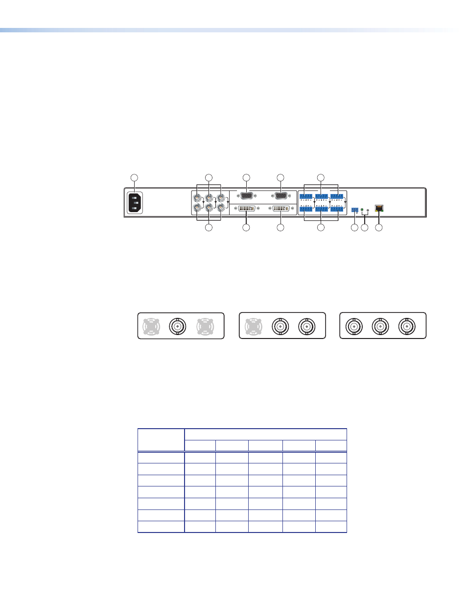
Rear Panel Features
The rear panel of the SME 100 is shown in figure 4 below.
RS-232
RESET
Tx Rx
100-240VAC
50/60 Hz
0.5A MAX
R-Y
Y/
VID
B-Y/
C
RGB/R-Y,Y,B-Y/YC/VID
DVI-D
BUFFERED LOOP
BUFFERED LOOP
1
1
2
INPUTS
AUDIO
3
L
R
2
L
R
3
L
R
LAN
ACT LINK
1
4
5
3
2
6
7
10
8
9
12
11
Figure 4.
SME 100 Rear Panel
a
AC power input (IEC connector) — Plug a standard IEC power cord into this
connector to connect the SME 100 to a 100 to 240 VAC, 50 Hz or 60 Hz power source.
b
Component, S-video, composite BNC connectors (Input 1) — Connect a video
input device to the component, S-video, composite BNC connectors. See figure 5
below to connect the necessary signal format.
1
B-Y/
C
S-video (YC)
Y
/
VID
R-Y
1
R-Y
Y
/
VID
B-Y
/
C
Component Video (Y, R-Y, B-Y)
Composite Video
1
Y/
VID
B-Y/
C
R-Y
Figure 5.
BNC Signal Format Connection Diagram
c
Component, S-video, composite BNC buffered loop connectors (optional) —
Connect a video output device to the component, S-video, composite BNC buffered
loop connectors. These connectors output the input device that is connected to
input 1 (
b
). See figure 5 above to connect the necessary signal format.
d
15-pin HD connector with EDID emulation (Input 2) — Connect a video input
device to the 15-pin HD connector. See figure 6 below for pin configurations.
Signal
Input 2 Configuration
Pin 1
Pin 2
Pin 3
Pin 13
Pin 14
RGBHV
R
G
B
H
V
RGBS
R
G
B
S
RGBcvS
R
G
B
S
RGsB
R
Gs
B
YUV
R-Y
Y
B-Y
S-video
Y
C
Video
Vid
Figure 6.
15-pin HD Connector Pin Configuration Table
SME 100 • Panels and Cabling
12