8 alarms, 1 transmit rai, Alarms – Rainbow Electronics DS26519 User Manual
Page 75: Table 9-25. t1 alarm criteria
DS26519 16-Port T1/E1/J1 Transceiver
75 of 310
9.9.8 Alarms
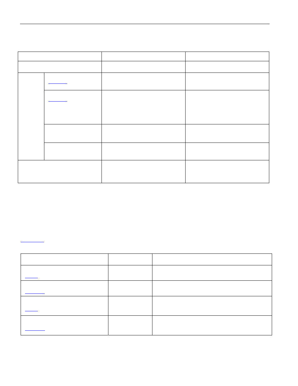
Table 9-25. T1 Alarm Criteria
ALARM
SET CRITERIA
CLEAR CRITERIA
AIS
(Blue Alarm) (See Note 1)
When over a 3ms window, 4 or
fewer zeros are received.
When over a 3ms window, 5 or
more zeros are received.
1) D4 Bit 2 Mode
(
.0 = 0)
When bit 2 of 256 consecutive
channels is set to zero for at least
254 occurrences.
When bit 2 of 256 consecutive
channels is set to zero for less than
254 occurrences.
2) D4 12th F-Bit Mode
(
.0 = 1)
(Note: This mode is
also referred to as the
“Japanese Yellow
Alarm.”)
When the 12th framing bit is set to
one for two consecutive
occurrences.
When the 12th framing bit is set to
zero for two consecutive
occurrences.
3) ESF Mode
When 16 consecutive patterns of
00FF appear in the FDL.
When 14 or fewer patterns of 00FF
hex out of 16 possible appear in the
FDL.
RAI
(Yellow
Alarm)
4) J1 ESF Mode (J1
LFA)
When 16 consecutive patterns of
FFFF appear in the FDL.*
When 14 or fewer patterns of FFFF
hex out of 16 possible appear in the
FDL.*
LOS
(Loss of Signal)
(Note: This alarm is also referred to
as receive carrier loss (RCL).)
When 192 consecutive zeros are
received.
When 14 or more ones out of 112
possible bit positions are received
starting with the first one received.
Note 1:
The definition of the Alarm Indication Signal (Blue Alarm) is an unframed all-ones signal. AIS detectors should be able to operate
properly in the presence of a 10E-3 error rate and they should not falsely trigger on a framed all-ones signal. The AIS alarm criteria
in the DS26519 has been set to achieve this performance. It is recommended that the RAIS bit be qualified with the RLOF bit.
Note 2:
The following terms are equivalent:
RAIS = Blue Alarm
RLOS = RCL
RLOF = Loss of Frame (conventionally RLOS for Dallas Semiconductor devices)
RRAI = Yellow Alarm
9.9.8.1 Transmit RAI
shows the registers related to the transmit RAI (Yellow Alarm).
Table 9-26. Registers Related to Transmit RAI (Yellow Alarm)
REGISTER
FRAMER 1
ADDRESSES
FUNCTION
Transmit Control Register 1
(
181h
Enable transmission of RAI.
Transmit Control Register 2
(
.TRAIS)
182h
Select RAI to be T1 or J1.
Transmit Control Register 4
(
186h
Select RAI to be normal or RAI-CI for T1 ESF mode.
Transmit Control Register 2
(
182h
Selects automatic remote alarm generation in E1
mode.
Note: The addresses shown above are for Framer 1.