T1rfdl, Is 8 bits, Registe – Rainbow Electronics DS26519 User Manual
Page 168: Update, E1rrts7
DS26519 16-Port T1/E1/J1 Transceiver
168 of 310
Register Name:
T1RFDL (T1 Mode)
Register Description:
Receive FDL Register
Register Address:
062h + (200h x (n - 1)) + (2000h x [(n - 1) / 8]): where n = 1 to 16
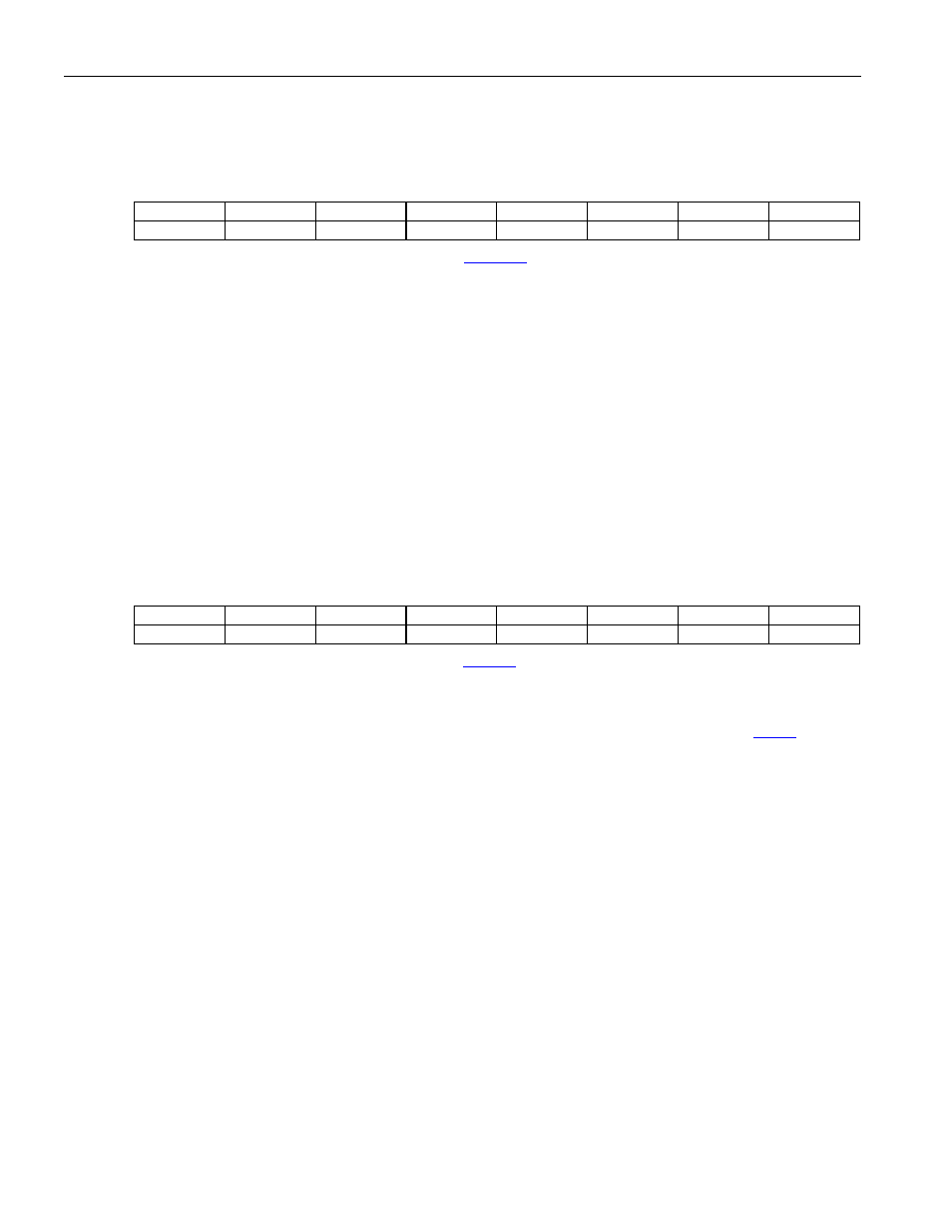
Bit
# 7 6 5 4 3 2 1 0
Name RFDL7 RFDL6 RFDL5 RFDL4 RFDL3 RFDL2 RFDL1 RFDL0
Default
0 0 0 0 0 0 0 0
Note: This register has an alternate definition for E1 mode. See
Bit 7: Receive FDL Bit 7 (RFDL7). MSB of the received FDL code.
Bit 6: Receive FDL Bit 6 (RFDL6).
Bit 5: Receive FDL Bit 5 (RFDL5).
Bit 4: Receive FDL Bit 4 (RFDL4).
Bit 3: Receive FDL Bit 3 (RFDL3).
Bit 2: Receive FDL Bit 2 (RFDL2).
Bit 1: Receive FDL Bit 1 (RFDL1).
Bit 0: Receive FDL Bit 0 (RFDL0). LSB of the received FDL code.
Register Name:
E1RRTS7 (E1 Mode)
Register Description:
Receive Real-Time Status Register 7
Register Address:
062h + (200h x (n - 1)) + (2000h x [(n - 1) / 8]): where n = 1 to 16
Bit
# 7 6 5 4 3 2 1 0
Name CSC5 CSC4 CSC3 CSC2 CSC0
CRC4SA
CASSA
FASSA
Default
0 0 0 0 0 0 0 0
Note: This register has an alternate definition for T1 mode. See
. All bits in this register are real-time (not latched).
Bits 7 to 3: CRC-4 Sync Counter Bits (CSC[5:2] and CSC0). The CRC-4 sync counter increments each time the
8ms CRC-4 multiframe search times out. The counter is cleared when the framer has successfully obtained
synchronization at the CRC-4 level. The counter can also be cleared by disabling the CRC-4 mode (
.3 = 0).
This counter is useful for determining the amount of time the framer has been searching for synchronization at the
CRC-4 level. ITU-T G.706 suggests that if synchronization at the CRC-4 level cannot be obtained within 400 ms,
then the search should be abandoned and proper action taken. The CRC-4 sync counter will saturate (not rollover).
CSC0 is the LSB of the 6–bit counter. (Note: CSC1 is omitted to allow resolution to > 400ms using 5 bits.)
Bit 2: CRC-4 MF Sync Active (CRC4SA). Set while the synchronizer is searching for the CRC-4 MF alignment
word.
Bit 1: CAS MF Sync Active (CASSA). Set while the synchronizer is searching for the CAS MF alignment word.
Bit 0: FAS Sync Active (FASSA). Set while the synchronizer is searching for alignment at the FAS level.