Jtag boundary scan and test access port, Figure 14-1. jtag functional block diagram – Rainbow Electronics DS26519 User Manual
Page 302
DS26519 16-Port T1/E1/J1 Transceiver
302 of 310
14.
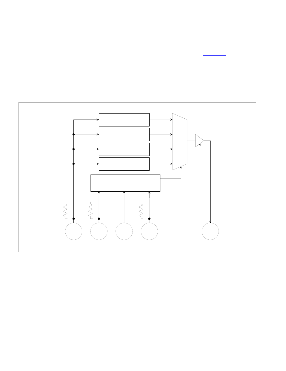
JTAG BOUNDARY SCAN AND TEST ACCESS PORT
The DS26519 IEEE 1149.1 design supports the standard instruction codes SAMPLE:PRELOAD, BYPASS, and
EXTEST. Optional public instructions included are HIGHZ, CLAMP, and IDCODE. See
. The DS26519
contains the following as required by IEEE 1149.1 Standard Test Access Port and Boundary Scan Architecture.
Test Access Port (TAP)
TAP Controller
Instruction Register
Bypass Register
Boundary Scan Register
Device Identification Register
The Test Access Port has the necessary interface pins:
JTRST, JTCLK, JTMS, JTDI, and JTDO. See the pin
descriptions for details.
Figure 14-1. JTAG Functional Block Diagram
JTDI JTMS
JTCLK
JTRST
JTDO
TEST ACCESS PORT
CONTROLLER
V
DD
V
DD
V
DD
BOUNDRY SCAN
REGISTER
BYPASS
REGISTER
INSTRUCTION
REGISTER
IDENTIFICATION
REGISTER
MUX
SELECT
OUTPUT ENABLE
10k
Ω
10k
Ω
10k
Ω