Rss1, Rss2, Rss3 – Rainbow Electronics DS26519 User Manual
Page 195: Rss4
DS26519 16-Port T1/E1/J1 Transceiver
195 of 310
Register Name:
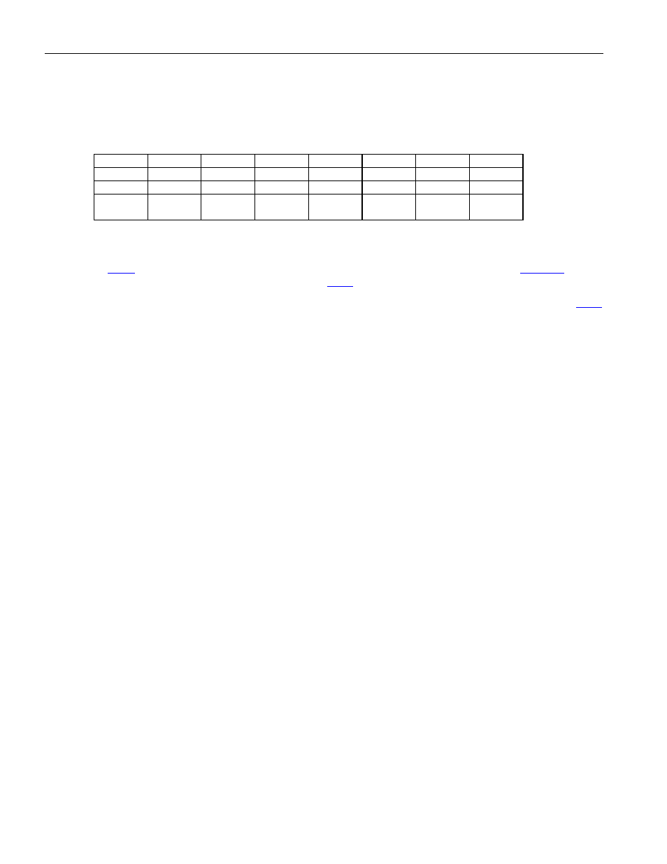
RSS1, RSS2, RSS3, RSS4
Register Description:
Receive-Signaling Status Registers 1 to 4
Register Address:
098h, 099h, 09Ah, 09Bh + (200h x (n - 1)) + (2000h x [(n - 1) / 8]): where n = 1 to 16
(MSB)
(LSB)
Bit
# 7 6 5 4 3 2 1 0
Name CH8 CH7 CH6 CH5 CH4 CH3 CH2 CH1*
RSS1
CH16 CH15 CH14 CH13 CH12 CH11 CH10 CH9 RSS2
CH24 CH23 CH22 CH21 CH20 CH19 CH18 CH17*
RSS3
CH32 CH31 CH30 CH29 CH28 CH27 CH26 CH25
RSS4 (E1
Mode Only)
Note: Status bits in this register are latched.
When a channel’s signaling data changes state, the respective bit in registers RSS1–4 will be set and latched. The
RSCOS bit (
.3) will be set if the channel was also enabled by setting the appropriate bit in
–4. The
INTB signal will go low if enabled by the interrupt mask bit
.3. The bit will remain set until read.
*
Note that in E1 CAS mode, the LSB of RSS1 would typically represent the CAS alignment bits, and the LSB of
represents reserved bits and the distant multiframe alarm.