T1rcr2, Rrais), Raiie) – Rainbow Electronics DS26519 User Manual
Page 159
DS26519 16-Port T1/E1/J1 Transceiver
159 of 310
Register Name:
T1RCR2 (T1 Mode)
Register Description:
Receive Control Register 2
Register Address:
014h + (200h x (n - 1)) + (2000h x [(n - 1) / 8]): where n = 1 to 16
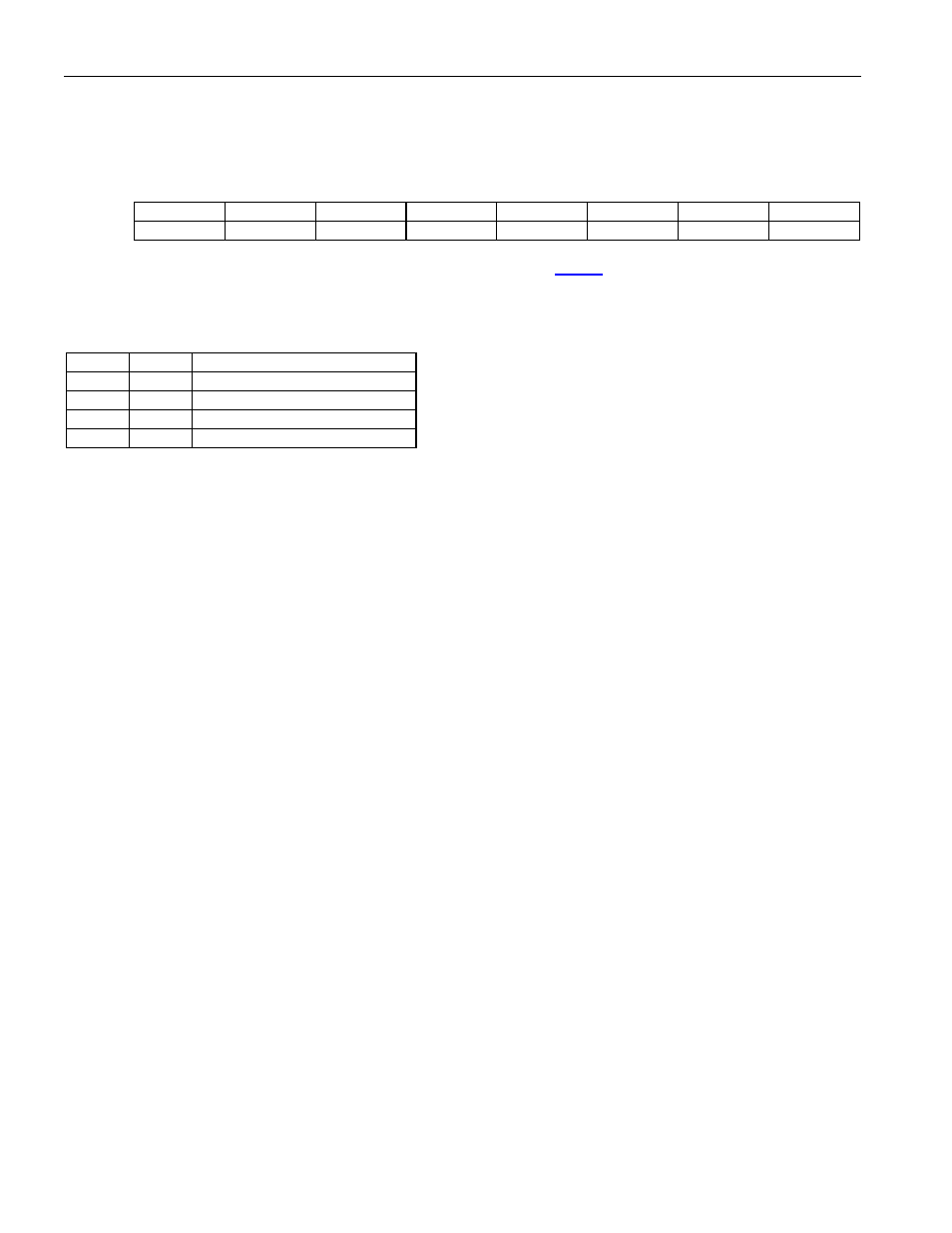
Bit
# 7 6 5 4 3 2 1 0
Name — — —
RSLC96
OOF2
OOF1
RAIIE
RRAIS
Default
0 0 0 0 0 0 0 0
Bit 4: Receive SLC-96 Synchronizer Enable (RSLC96). See Section
for SLC-96 details.
0 = The SLC-96 synchronizer is disabled.
1 = The SLC-96 synchronizer is enabled.
Bits 3 and 2: Out Of Frame Select Bits (OOF[2:1])
OOF2
OOF1
OUT OF FRAME CRITERIA
0
0
2/4 frame bits in error
0
1
2/5 frame bits in error
1
0
2/6 frame bits in error
1
1
2/6 frame bits in error
Bit 1: Receive RAI Integration Enable (RAIIE). The ESF RAI indication can be interrupted for a period not to
exceed 100ms per interruption (T1.403). In ESF mode, setting RAIIE will cause the RAI status from the DS26519
to be integrated for 200ms.
0 =
RAI detects when 16 consecutive patterns of 00FF appear in the FDL.
RAI clears when 14 or fewer patterns of 00FF hex out of 16 possible appear in the FDL.
1 =
RAI detects when the condition has been present for greater than 200ms.
RAI clears when the condition has been absent for greater than 200ms.
Bit 0: Receive-Side Remote Alarm Select (RRAIS)
0 = Receive framer detects T1 remote alarm.
D4—Zeros in bit 2 of all channels.
ESF—00FF pattern in FDL.
1 = Receive Framer detects J1 Remote Alarm.
D4—A one in the S-bit position of frame 12.
ESF—all ones in FDL.