Rainbow Electronics DS26519 User Manual
Page 22
DS26519 16-Port T1/E1/J1 Transceiver
22 of 310
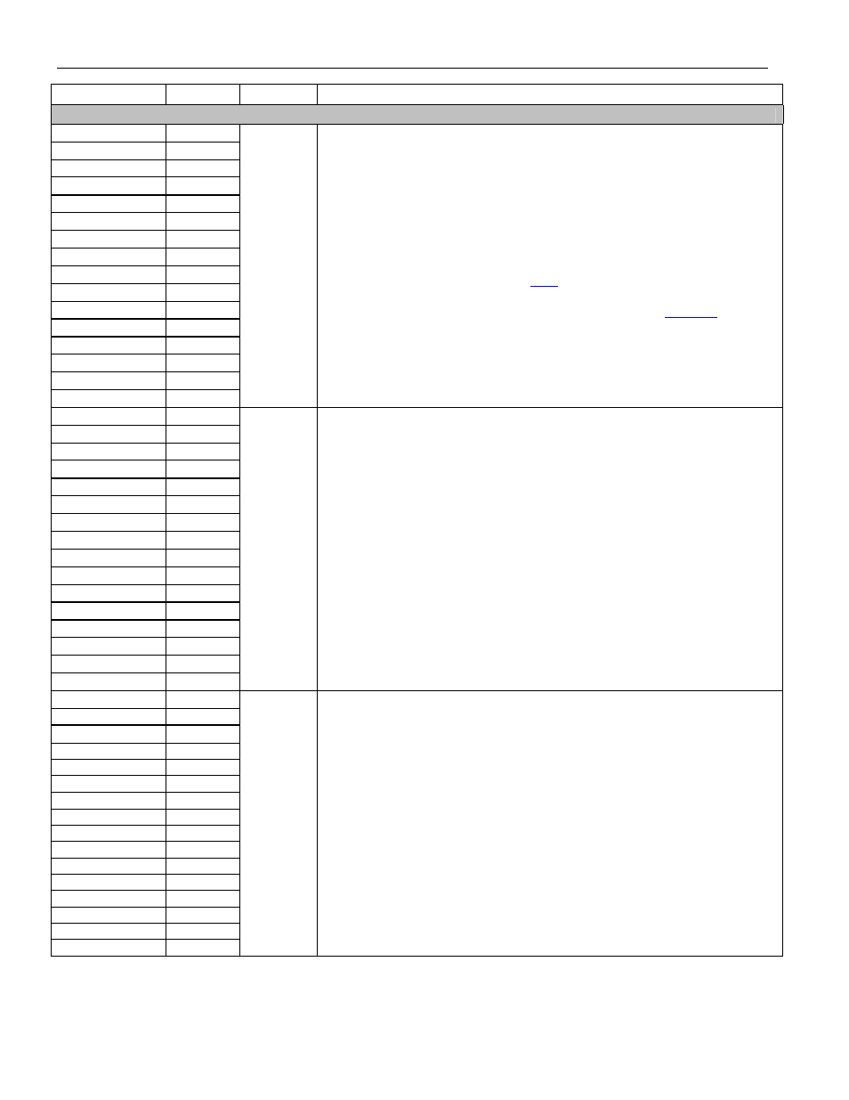
NAME PIN
TYPE
FUNCTION
TRANSMIT FRAMER
TSER1 B15
TSER2 D14
TSER3 T8
TSER4 R12
TSER5 T10
TSER6 U11
TSER7 C17
TSER8 E17
TSER9 U21
TSER10 R20
TSER11 W6
TSER12 C1
TSER13 E1
TSER14 H1
TSER15 H15
TSER16 F17
Input
Transmit NRZ Serial Data.
These pins are sampled on the falling edge of
TCLKn when the transmit-side elastic store is disabled. These pins are sampled
on the falling edge of TSYSCLKn when the transmit-side elastic store is enabled.
In IBO mode, data for multiple framers can be used in high-speed multiplexed
scheme. This is described in Section
. The table there presents the
combination of framer data for each of the streams.
TSYSCLKn is used as a reference when IBO is invoked. See
.
TCLK1 F7
TCLK2 G10
TCLK3 R8
TCLK4 AB4
TCLK5 AB6
TCLK6 AB8
TCLK7 B21
TCLK8 D18
TCLK9 K14
TCLK10 P16
TCLK11 W5
TCLK12 M18
TCLK13 N8
TCLK14 N7
TCLK15 P21
TCLK16 D17
Input
Transmit Clock 1 to 16.
A 1.544MHz or a 2.048MHz primary clock. Used to
clock data through the transmit side of the transceiver. TSERn data is sampled
on the falling edge of TCLKn. TCLKn is used to sample TSERn when the elastic
store is not enabled or IBO is not used.
TSYSCLK1 W11
TSYSCLK2 A16
TSYSCLK3 K8
TSYSCLK4 U7
TSYSCLK5 V10
TSYSCLK6 U14
TSYSCLK7 C18
TSYSCLK8 Y21
TSYSCLK9 L4
TSYSCLK10 R19
TSYSCLK11 E2
TSYSCLK12 AA3
TSYSCLK13 J1
TSYSCLK14 J2
TSYSCLK15 E16
TSYSCLK16 M17
Input
Transmit System Clock 1 to 16.
1.544MHz, 2.048MHz, 4.096MHz, 8.192MHz,
or 16.384MHz clock. Only used when the transmit-side elastic store function is
enabled. Should be tied low in applications that do not use the transmit-side
elastic store. The clock can be 4.096MHz, 8.912MHz, or 16.384MHz when IBO
mode is used.