7 precautions on mounting – Epson S1C33210 User Manual
Page 80
7 PRECAUTIONS ON MOUNTING
A-66
EPSON
S1C33210 PRODUCT PART
7 Precautions on Mounting
The following shows the precautions when designing the board and mounting the IC.
Oscillation Circuit
• Oscillation characteristics change depending on conditions (board pattern, components used, etc.).
In particular, when a ceramic oscillator or crystal oscillator is used, use the oscillator manufacturer's
recommended values for constants such as capacitance and resistance.
• Disturbances of the oscillation clock due to noise may cause a malfunction. Consider the following points to
prevent this:
(1) Components which are connected to the OSC3 (OSC1), OSC4 (OSC2) and PLLC pins, such as oscillators,
resistors and capacitors, should be connected in the shortest line.
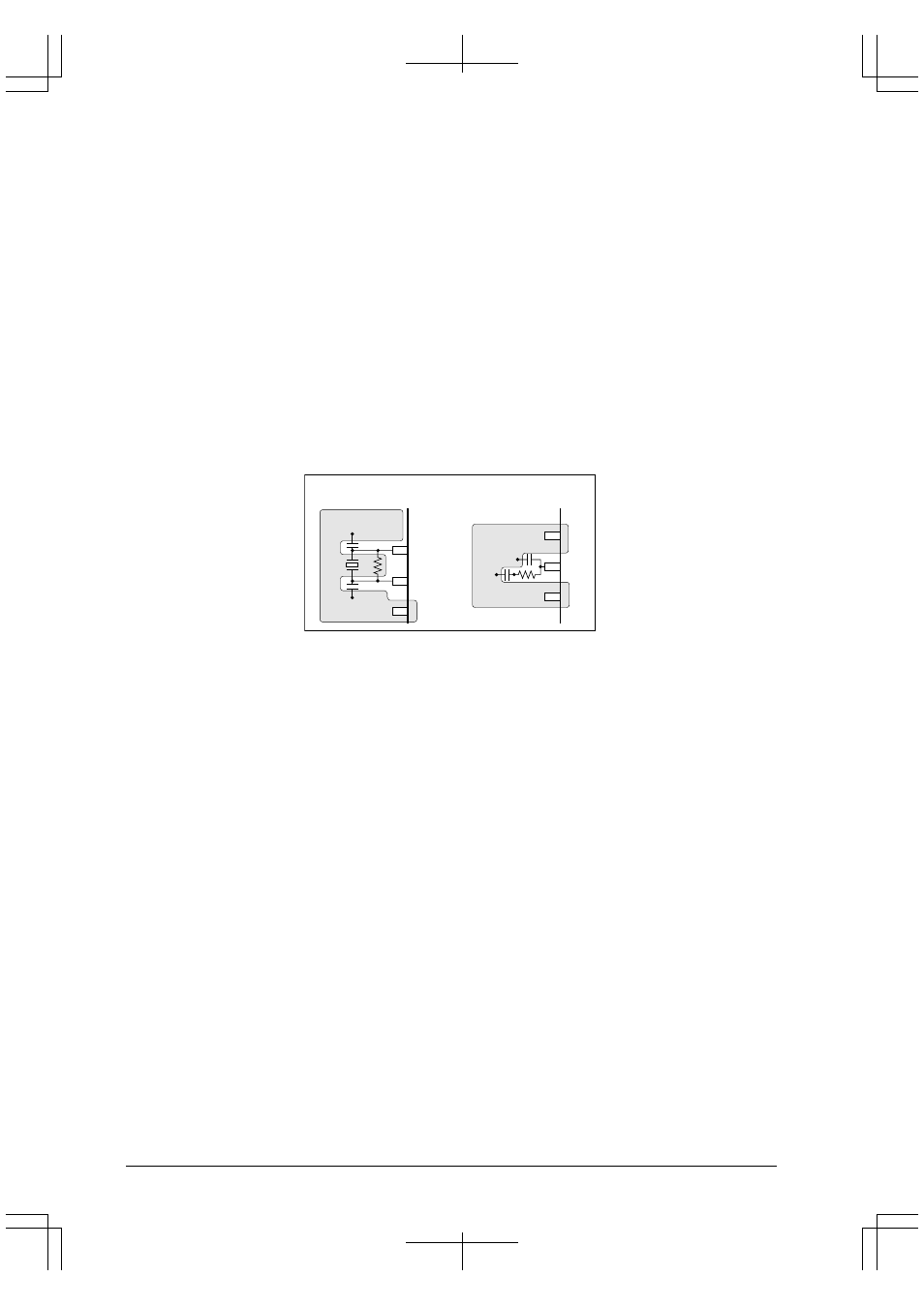
(2) As shown in the figure below, make a V
SS
pattern as large as possible at circumscription of the OSC3
(OSC1) and OSC4 (OSC2) pins and the components connected to these pins. The same applies to the
PLLC pin.
Furthermore, do not use this V
SS
pattern to connect other components than the oscillation system.
OSC4
OSC3
V
SS
Sample V
SS
pattern
OSC3 and OSC4
V
SS
PLLC
V
SS
PLLC
(3) When supplying an external clock to the OSC3 (OSC1) pin, the clock source should be connected to the
OSC3 (OSC1) pin in the shortest line.
Furthermore, do not connect anything else to the OSC4 (OSC2) pin.
• In order to prevent unstable operation of the oscillation circuit due to current leak between OSC3 (OSC1) and
V
DD
, please keep enough distance between OSC3 (OSC1) and V
DD
or other signals on the board pattern.
Reset Circuit
• The power-on reset signal which is input to the #RESET pin changes depending on conditions (power rise time,
components used, board pattern, etc.). Decide the time constant of the capacitor and resistor after enough tests
have been completed with the application product.
• In order to prevent any occurrences of unnecessary resetting caused by noise during operating, components
such as capacitors and resistors should be connected to the #RESET pin in the shortest line.
Power Supply Circuit
• Sudden power supply variation due to noise may cause malfunction. Consider the following points to prevent
this:
(1) The power supply should be connected to the V
DD
, V
SS
and AV
DD
pins with patterns as short and large as
possible.
In particular, the power supply for AV
DD
affects A/D conversion precision.