Memory area, Memory map – Epson S1C33210 User Manual
Page 156
II CORE BLOCK: BCU (Bus Control Unit)
B-II-4-4
EPSON
S1C33210 FUNCTION PART
Memory Area
Memory Map
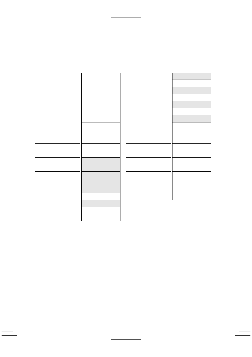
Figure 4.1 shows the memory map supported by the BCU.
Internal RAM
Internal I/O
(Mirror of internal I/O)
(Mirror of internal I/O)
(Reserved)
For CPU core or debug mode
(Reserved)
For middleware use
0x0BFFFFF
0x0800000
0x07FFFFF
0x0600000
0x05FFFFF
0x0400000
0x03FFFFF
0x0380000
0x037FFFF
0x0300000
0x02FFFFF
0x0200000
0x01FFFFF
0x0100000
0x00FFFFF
0x0080000
0x007FFFF
0x0060000
0x005FFFF
0x0050000
0x004FFFF
0x0040000
0x003FFFF
0x0030000
0x002FFFF
0x0000000
Area
Area 9
SRAM type
Burst ROM type
8 or 16 bits
Area 8
SRAM type
DRAM type
8 or 16 bits
Area 7
SRAM type
DRAM type
8 or 16 bits
Area 6
SRAM type
Area 5
SRAM type
Area 4
SRAM type
8 or 16 bits
Area 3
16 bits
Fixed at 1 cycle
Area 2
16 bits
Fixed at 3 cycles
Area 1
8, 16 bits
2 or 4 cycles
Area 0
32 bits
Fixed at 1 cycle
Address
External memory (1MB)
Internal I/O memory
External memory (2MB)
External memory (2MB)
External memory (4MB)
External memory (4MB)
External I/O (8-bit device)
External I/O (16-bit device)
0xFFFFFFF
0xD000000
0xCFFFFFF
0xC000000
0xBFFFFFF
0x9000000
0x8FFFFFF
0x8000000
0x7FFFFFF
0x7000000
0x6FFFFFF
0x6000000
0x5FFFFFF
0x5000000
0x4FFFFFF
0x4000000
0x3FFFFFF
0x3000000
0x2FFFFFF
0x2000000
0x1FFFFFF
0x1800000
0x17FFFFF
0x1000000
0x0FFFFFF
0x0C00000
Area
Area 18
SRAM type
8 or 16 bits
Area 17
SRAM type
8 or 16 bits
Area 16
SRAM type
8 or 16 bits
Area 15
SRAM type
8 or 16 bits
Area 14
SRAM type
DRAM type
8 or 16 bits
Area 13
SRAM type
DRAM type
8 or 16 bits
Area 12
SRAM type
8 or 16 bits
Area 11
SRAM type
8 or 16 bits
Area 10
SRAM type
Burst ROM type
8 or 16 bits
Address
External memory (8MB)
External memory (8MB)
External memory (16MB)
External memory (16MB)
External memory (16MB)
External memory (16MB)
External memory (16MB)
External memory (16MB)
Figure 4.1 Memory Map
Basically, Areas 0 to 3 are internal memory areas and Areas 4 to 18 are external memory areas.
Area 0 is normally used for a built-in RAM. The built-in memory is mapped from the beginning of the area.
Area 1 is reserved for the I/O memory of the on-chip functional blocks. Address 0x0040000 to address 0x004FFFF
are used as the control registers and address 0x0050000 to 0x005FFFF are used as the mirror area.
Area 2 is used in debug mode only and it cannot be accessed in user mode (normal program execution status).
Area 3 is reserved for S1C33 middlewares.
Area 4 to 18 can also be configured as internal memory areas using the control register and they can be used for user
logic circuits.
And Area 5 is used as an internal I/O area.