Bus operation, Data arrangement in memory, Bus operation of external memory – Epson S1C33210 User Manual
Page 164
II CORE BLOCK: BCU (Bus Control Unit)
B-II-4-12
EPSON
S1C33210 FUNCTION PART
Bus Operation
Data Arrangement in Memory
The S1C33 Family of devices handle data in bytes (8 bits), half-words (16 bits), and words (32 bits). When
accessing data in memory, it is necessary to specify a boundary address that conforms to the data size involved.
Specification of an invalid address causes an address error exception. For instructions (e.g., stack manipulation or
branch instructions) that rewrite the SP (stack pointer) or PC (program counter), the specified addresses are forcibly
modified to appropriate boundary addresses. Therefore, no address error exception occurs in this type of instruction.
For details about the address error exception, refer to the "S1C33000 Core CPU Manual".
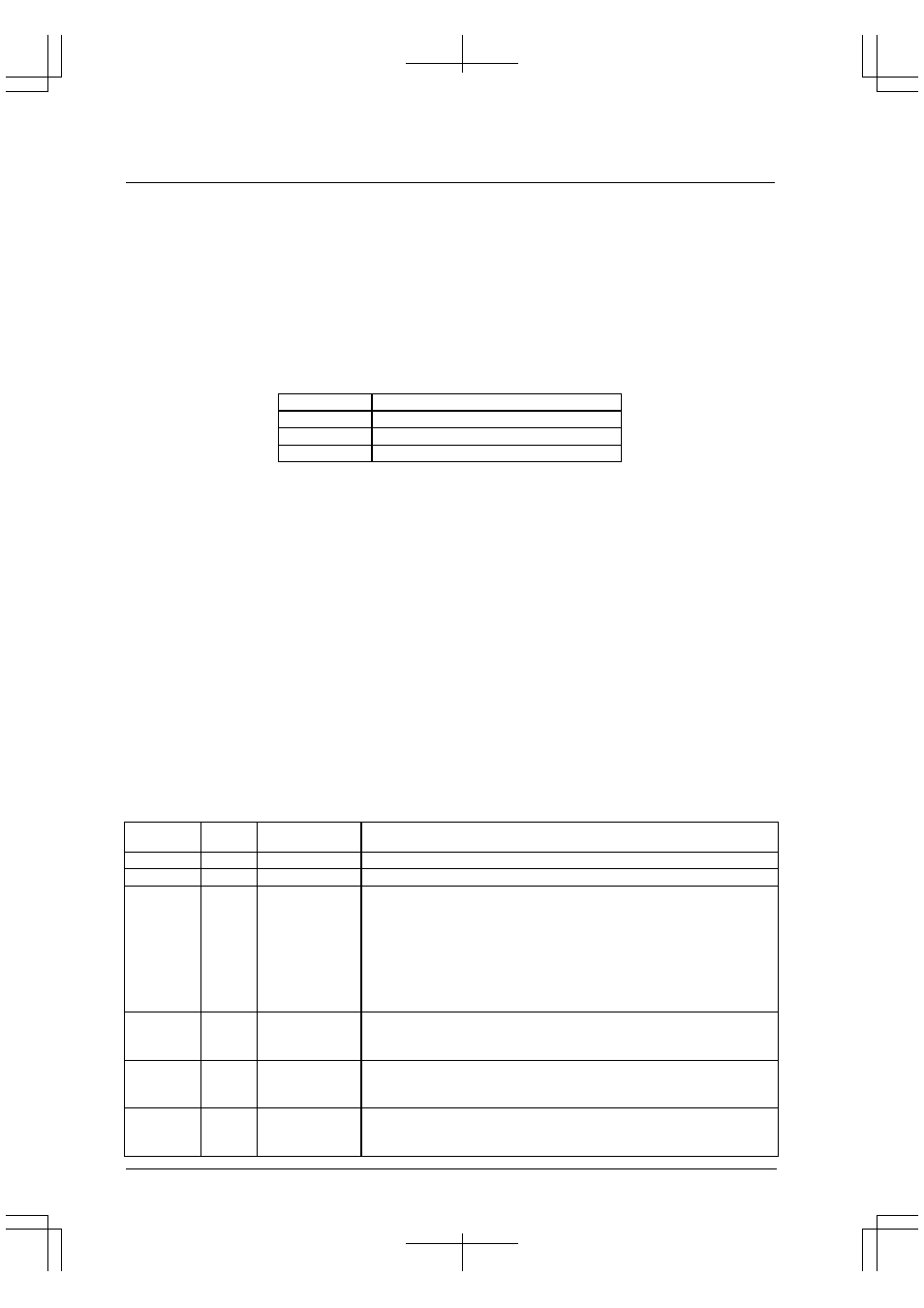
Table 4.10 shows the data arrangement in memory, classified by data type.
Table 4.10 Data Arrangement in Memory
Data type
Arranged location
Byte data
Byte boundary address (all addresses)
Half-word data
Half-word boundary address (A[0]="0")
Word data
Word boundary address (A[1:0]="00")
The half-word and word data in memory area accessed in little-endian format by default. It can be changed to big-
endian format using AxxEC (D[7:0])/Access control register (0x48132). When "1" is written to AxxEC, the
corresponding area is accessed in big-endian method. The bit names and the corresponding areas are as follows:
A18EC (D7): Areas 17 and 18
A16EC (D6): Areas 15 and 16
A14EC (D5): Areas 13 and 14
A12EC (D4): Areas 11 and 12
A10EC (D3): Areas 9 and 10 ... Fixed at "0" (little-endian) for booting.
A8EC (D2):
Areas 7 and 8
A6EC (D1):
Area 6
A5EC (D0):
Areas 4 and 5
To increase memory efficiency, try to locate the same type of data at continuous locations on exact boundary
addresses in order to minimize invalid areas.
Bus Operation of External Memory
The external data bus is 16-bits wide. For this reason, more than one bus operation occurs depending on the device
size and the data size of the instruction executed, as shown in Table 4.11.
Table 4.11 Number of Bus Operation Cycles
Data size to
be accessed
Devise
size
Number of bus
operation cycles
Remarks
32 bits
16 bits
2
16 bits
16 bits
1
8 bits
16 bits
1
In little-endian method, the low-order byte is accessed when the LSB of
the address (A[0]) is "0" or the #BSL signal is L. The high-order byte is
accessed when the LSB of the address (A[0]) is "1" or the #BSH signal is
H.
In big-endian method, the high-order byte is accessed when the LSB of the
address (A[0]) is "0" or the #BSL signal is L. The low-order byte is
accessed when the LSB of the address (A[0]) is "1" or the #BSH signal is
H.
32 bits
8 bits
4
In little-endian method, the 8-bit device must be connected to the low-order
8 bits of the data bus. In big-endian method, the 8-bit device must be
connected to the high-order 8 bits of the data bus.
16 bits
8 bits
2
In little-endian method, the 8-bit device must be connected to the low-
order 8 bits of the data bus. In big-endian method, the 8-bit device must be
connected to the high-order 8 bits of the data bus.
8 bits
8 bits
1
In little-endian method, the 8-bit device must be connected to the low-
order 8 bits of the data bus. In big-endian method, the 8-bit device must be
connected to the high-order 8 bits of the data bus.