Communications mode, Phs signal format – Epson S1C33210 User Manual
Page 391
III PERIPHERAL BLOCK: MONITORED MOBILE ACCESS INTERFACES
S1C33210 FUNCTION PART
EPSON
B-III-10-5
Communications Mode
Next configure the mobile access interface pins with the MSEL pin input level and communications macro
select (MCRS) register (D[1:0]/0x200000). (See Table 10.4.)
The default MCRS setting, after an initial reset, is 00, which specifies UART or serial IF Ch. 3.
Table 10.4 Communications Mode
MSEL Input
Level
MCRS1
MCRS0
Communications
Mode
Target Mobile Device
High
1
1
PHS
communications
PHS
High
1
0
PDC
communications
PDC
High
0
1
HDLC
communications
PDC device supporting
packets
High
0
0
UART
communications
CdmaOne
Low
0
0
Serial IF Ch. 3
PHS Signal Format
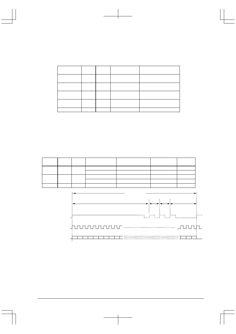
Next use the BMODE, BHALF, and FMODE bits in the communications block PHS mode settings register
(D[2:0]/0x0200010) to configure the PHS signal format to match the target PHS device. Table 10.5 and Figure
10.2 through Figure 10.6 summarize the signal formats available.
Use only the combinations given.
The default setting, after an initial reset, BMODE, BHALF and FMODE are set to 000.
These settings are ignored by all communications modes other than PHS.
Table 10.5 PHS Signal Formats
BMODE
BHALF FMODE
Frame Signal
Frequency
Bit Clock Frequency
Data Transfer
Rate
Figure
0
0
0
200 Hz (5ms)
32 kHz
32 kbps
Figure 10.2
200 Hz (5ms)
64 kHz
64 kbps
Figure 10.3
1
0
1
8 kHz
32 kHz
32 kbps
Figure 10.4
8 kHz
64 kHz
64 kbps
Figure 10.5
1
1
1
8 kHz
64 kHz
32 kbps
Figure 10.6
32 kbps: 20 ms
DCD (frame signal)
Frame signal period
PIAFS frame period
CTS (bit clock, 32 kHz)
TXD and RXD (data signals)
5 ms
5 ms
5 ms
5 ms
0
1
2
3
4
5
6
7
8
(Total 640 bits)
Figure 10.2 PHS Signal Format (1)