Oscillator types – Epson S1C33210 User Manual
Page 298
III PERIPHERAL BLOCK: LOW-SPEED (OSC1) OSCILLATION CIRCUIT
B-III-6-2
EPSON
S1C33210 FUNCTION PART
Oscillator Types
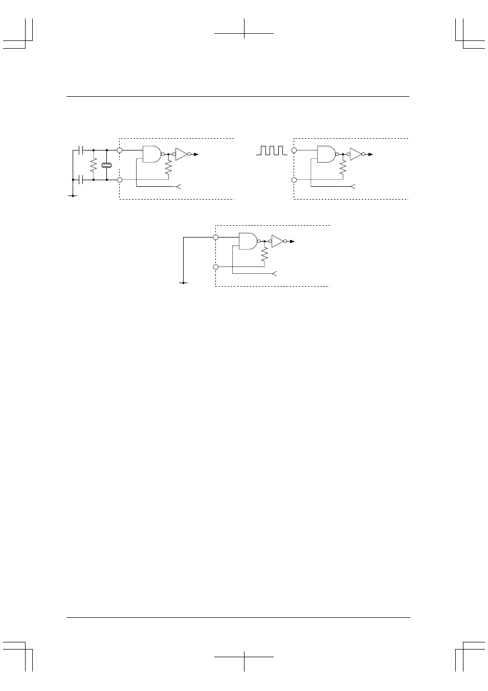
In the low-speed (OSC1) oscillation circuit, either a crystal oscillation or an external clock input can be selected as the
type of oscillation circuit.
Figure 6.2 shows the structure of the low-speed (OSC1) oscillation circuit.
V
SS
OSC2
OSC1
R
f
C
D1
C
G1
Oscillation circuit
control signal
Oscillation circuit
control signal
X'tal1
f
OSC1
OSC2
OSC1
External
clock
N.C.
V
SS
V
DD
f
OSC1
(1) Crystal oscillation circuit
V
SS
OSC2
OSC1
Oscillation circuit
control signal
Low level
(3) When not used
(2) External clock input
Figure 6.2 Low-Speed (OSC1) Oscillation Circuit
When using a crystal oscillation for this circuit, connect a crystal resonator X'tal1 (32.768 kHz, Typ.) and feedback
resistor (Rf) between the OSC1 and OSC2 pins, and two capacitors (C
G1
, C
D1
) between the OSC1 pin and V
SS
and
the OSC2 pin and V
SS
, respectively.
When an external clock source is used, leave the OSC2 pin open and input a square-wave clock to the OSC1 pin.
If the low-speed (OSC1) oscillation circuit is not used, connect the OSC1 pin to V
SS
and leave the OSC2 pin open.
The oscillation frequency is 32.768 kHz (Typ.). Use a crystal resonator or external clock that oscillates at this
frequency. No other frequency can be used for clock applications.
For details on oscillation characteristics and the external clock input characteristics, refer to "Electrical
Characteristics".