Epson S1C33210 User Manual
Page 490
V DMA BLOCK: IDMA (Intelligent DMA)
B-V-3-2
EPSON
S1C33210 FUNCTION PART
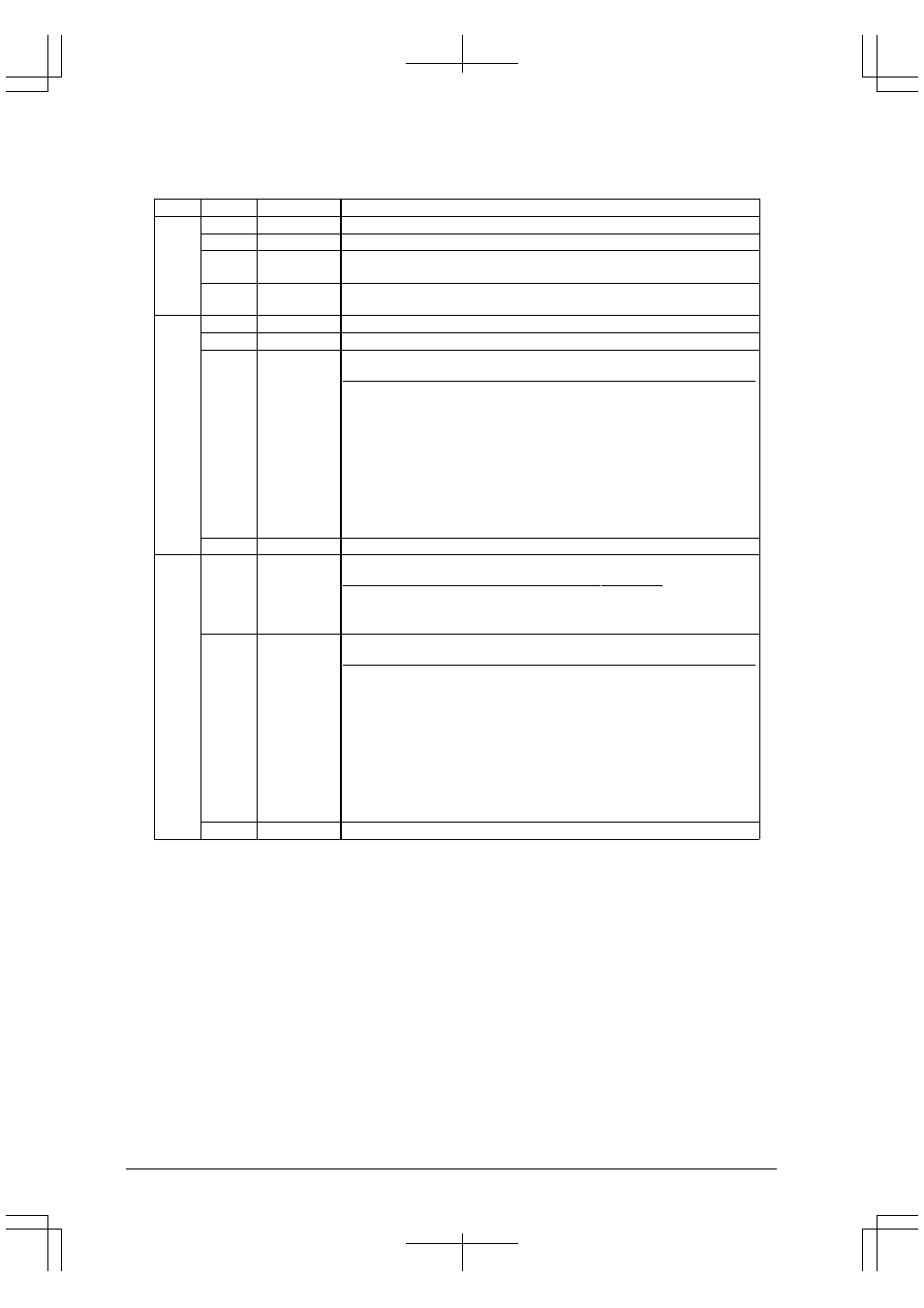
The contents of control information (3 words) in each channel are shown in the table below.
Table 3.1 IDMA Control Information
Word
Bit
Name
Function
1st
D31
LNKEN
IDMA link enable
"1" = Enabled, "0" = Disabled
D30–24
LNKCHN[6:0] IDMA link field
D23–8
TC[15:0]
Transfer counter (block transfer mode)
Transfer counter - high-order 16 bits (single or successive transfer mode)
D7–0
BLKLEN[7:0]
Block size (block transfer mode)
Transfer counter - low-order 8 bits (single or successive transfer mode)
2nd
D31
DINTEN
End-of-transfer interrupt enable
"1" = Enabled, "0" = Disabled
D30
DATSIZ
Data size control
"1" = Half-word, "0" = Byte
D29–28
SRINC[1:0]
Source address control
SRINC1 SRINC0 Setting contents
1
1
Address incremented
(In block transfer mode, the transfer address is
updated without reset using the initial value.)
1
0
Address incremented
(In block transfer mode, the transfer address is
updated with the initial value.)
0
1
Address decremented
(In block transfer mode, the transfer address is
updated without reset using the initial value.)
0
0
Address fixed
D27–0
SRADR[27:0] Source address
3rd
D31–30
DMOD[1:0]
Transfer mode (Do not set to "11".)
DMOD1 DMOD0 Setting contents
1
0
Block transfer mode
0
1
Successive transfer mode
0
0
Single transfer mode
D29–28
DSINC[1:0]
Destination address control
DSINC1 DSINC0 Setting contents
1
1
Address incremented
(In block transfer mode, the transfer address is
updated without reset using the initial value.)
1
0
Address incremented
(In block transfer mode, the transfer address is
updated with the initial value.)
0
1
Address decremented
(In block transfer mode, the transfer address is
updated without reset using the initial value.)
0
0
Address fixed
D27–0
DSADR[27:0] Destination address
LNKEN: IDMA link enable (D31/1st Word)
If this bit remains set (= "1"), the IDMA channel that is set in the IDMA link field is invoked after the
completion of a DMA transfer in this channel. DMA transfers in multiple channels can be performed
successively by merely triggering the first channel to be executed. There is no limit to the number of channels
linked. Set this link in order of the IDMA channels you want to be executed.
If this bit is "0", IDMA is completed by merely executing a DMA transfer in this channel.
LNKCHN[6:0]: IDMA link field (D[30:24]/1st Word)
If you want IDMA to be linked, set the channel numbers (0 to 127) to be executed next.
The data in this field is valid only when LINKEN = "1".
TC[15:0]: Transfer counter (D[23:8]/1st Word)
In block transfer mode, a transfer count can be specified using up to 16 bits. Set this value here. In single transfer
and successive transfer modes, a transfer count can be specified using up to 24 bits. Set a 16-bit high-order
value here.