I/o memory of clock generator – Epson S1C33210 User Manual
Page 230
II CORE BLOCK: CLG (Clock Generator)
B-II-6-6
EPSON
S1C33210 FUNCTION PART
I/O Memory of Clock Generator
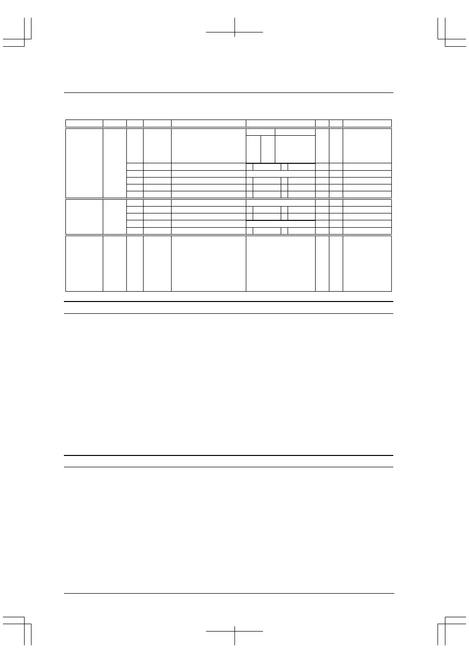
Table 6.4 lists the control bits of clock generator.
Table 6.4 Control Bits of Clock Generator
Name
Address
Register name
Bit
Function
Setting
Init.
R/W
Remarks
CLKDT1
CLKDT0
PSCON
–
CLKCHG
SOSC3
SOSC1
D7
D6
D5
D4–3
D2
D1
D0
System clock division ratio
selection
Prescaler On/Off control
reserved
CPU operating clock switch
High-speed (OSC3) oscillation On/Off
Low-speed (OSC1) oscillation On/Off
1 On
0 Off
1 OSC3
0 OSC1
1 On
0 Off
1 On
0 Off
0
0
1
0
1
1
1
R/W
R/W
–
R/W
R/W
R/W
Writing 1 not allowed.
0040180
(B)
1
1
0
0
1
0
1
0
CLKDT[1:0]
Division ratio
1/8
1/4
1/2
1/1
–
Power control
register
–
HLT2OP
8T1ON
–
PF1ON
D7–4
D3
D2
D1
D0
–
HALT clock option
OSC3-stabilize waiting function
reserved
OSC1 external output control
–
0
1
0
0
–
R/W
R/W
–
R/W
0 when being read.
Do not write 1.
0040190
(B)
1 On
0 Off
1 Off
0 On
1 On
0 Off
–
–
Clock option
register
Writing 10010110 (0x96)
removes the write protection of
the power control register
(0x40180) and the clock option
register (0x40190).
Writing another value set the
write protection.
CLGP7
CLGP6
CLGP5
CLGP4
CLGP3
CLGP2
CLGP1
CLGP0
D7
D6
D5
D4
D3
D2
D1
D0
Power control register protect flag
0
0
0
0
0
0
0
0
R/W
004019E
(B)
Power control
protect register
SOSC1: Low-speed (OSC1) oscillation control (D0) / Power control register (0x40180)
Turns the low-speed (OSC1) oscillation on or off.
Write "1": OSC1 oscillation turned on
Write "0": OSC1 oscillation turned off
Read: Valid
The oscillation of the low-speed (OSC1) oscillation circuit is stopped by writing "0" to SOSC1, and started again by
writing "1".
Since a duration of maximum three seconds is required for oscillation to stabilize after the oscillation has been
restarted, at least this length of time must pass before the OSC1 clock can be used.
Writing to SOSC1 is allowed only when CLGP[7:0] is set to "0b10010110". Note also that if the CPU is operating
using the OSC1 clock, writing "0" to SOSC1 is ignored and the oscillation is not turned off.
At initial reset, SOSC1 is set to "1" (OSC1 oscillation turned on).
Note: This control bit is effective only when the low-speed (OSC1) oscillation circuit in the Peripheral
Block is used.
SOSC3: High-speed (OSC3) oscillation control (D1) / Power control register (0x40180)
Turns the high-speed (OSC3) oscillation on or off.
Write "1": OSC3 oscillation turned on
Write "0": OSC3 oscillation turned off
Read: Valid
The oscillation of the high-speed (OSC3) oscillation circuit is stopped by writing "0" to SOSC3, and started again by
writing "1".
Since a duration of maximum 10 ms (for a 3.3-V crystal resonator) is required for oscillation to stabilize after the
oscillation has been restarted, at least this length of time must pass before the OSC3 clock can be used.
Writing to SOSC3 is allowed only when CLGP[7:0] is set to "0b10010110". Note also that if the CPU is operating
using the OSC3 clock, writing "0" to SOSC3 is ignored and the oscillation is not turned off.
At initial reset, SOSC3 is set to "1" (OSC3 oscillation turned on).