2 power supply, 1 power supply pins, 2 operating voltage (vdd, vss) – Epson S1C33210 User Manual
Page 25: 2 operating voltage (v
2 POWER SUPPLY
S1C33210 PRODUCT PART
EPSON
A-11
2 Power Supply
This chapter explains the operating voltage of the S1C33210.
2.1 Power Supply Pins
The S1C33210 has the power supply pins shown in Table 2.1.1.
Table 2.1.1 Power Supply Pins
Pin name
Pin No.
Function
QFP15-128
V
DD
8, 27, 47, 74, 93, 111 Power supply (+)
V
SS
3, 22, 39, 54, 67, 90,
102, 104
Power supply (-); GND
AV
DD
30
Analog system power supply (+); AV
DD
= V
DD
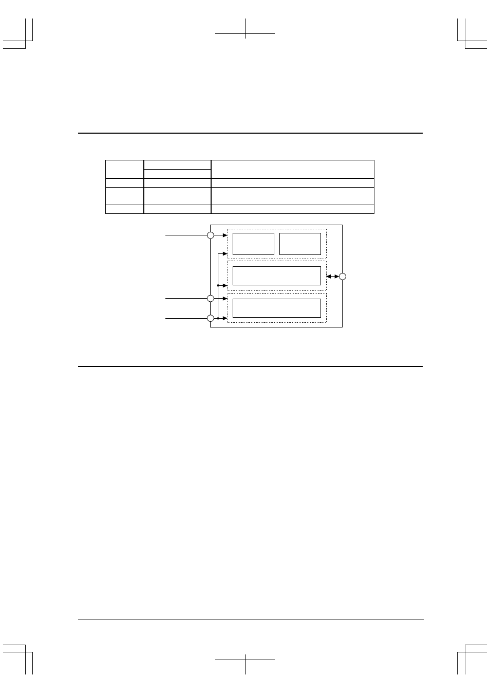
I/O
interface circuit
CPU core
Internal
peripheral
circuit
V
DD
2.7 to 3.6 V
2.7 to 3.6 V
GND
I/O pins
Analog circuits
(A/D converter)
AV
DD
V
SS
Figure 2.1.1 Power Supply System
2.2 Operating Voltage (V
DD
, V
SS
)
The core CPU, internal peripheral circuits, and external signal interfaces operate on the voltage difference between
the V
DD
and V
SS
pins. The following operating voltage can be used:
V
DD
= 2.7 V to 3.6 V (V
SS
= GND)
Note: The S1C33210 has 6 V
DD
pins and 8 V
SS
pins. Be sure to supply the operating voltage to all the
pins. Do not open any of them.
The operating clock frequency range (OSC3) is 5 MHz to 50 MHz with this voltage.