Controlling oscillation – Epson S1C33210 User Manual
Page 227
II CORE BLOCK: CLG (Clock Generator)
S1C33210 FUNCTION PART
EPSON
B-II-6-3
PLL
The PLL inputs the OSC3 clock and multiply its frequency. The multiply mode should be set using the PLLS[1:0]
pins according to the OSC3 clock frequency.
Table 6.2 Setting the PLLS[1:0] Pins
PLLS1
PLLS0
Mode
fin (OSC3 clock)
fout
1
1
x2
10 to 25 MHz
20 to 50 MHz
0
1
x4
10 to 12.5 MHz
20 to 50 MHz
0
0
PLL
Not used
–
Not used
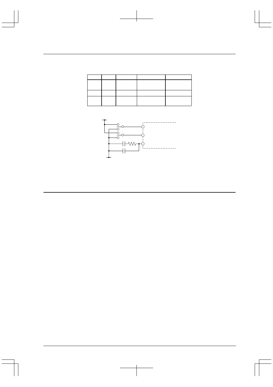
Figure 6.3 shows a basic external connection diagram for the PLL pins.
V
SS
PLLS1
PLLS0
PLLC
PLL
100 pF
10 pF
4.7 k
Ω
V
DD
Figure 6.3 External Connection Diagram
Note: When the PLL is not used, the OSC3 oscillation output is used as the source clock. In this case, the
oscillation frequency range is 10 MHz to 33 MHz. Furthermore, leave the PLLC pin open.
Controlling Oscillation
The high-speed (OSC3) oscillation circuit can be turned on or off using SOSC3 (D1) / Power control register
(0x40180).
The oscillation circuit is turned off by writing "0" to SOSC3 and turned back on again by writing "1". SOSC3 is set
to "1" at initial reset, so the oscillation circuit is turned on.
Notes: • When the high-speed (OSC3) oscillation circuit is used as the clock source for the CPU
operating clock, it cannot be turned off. In this case, writing "0" to SOSC3 is ignored. Note also
that writing to SOSC3 is allowed only when the power-control register protection flag is set to
"0b10010110".
• Immediately after the oscillation circuit is turned on, a certain period of time is required for
oscillation to stabilize (for 3.3-V crystal resonator, this time is 10 ms max.). To prevent the device
from operating erratically, do not use the clock until its oscillation has stabilized.
The high-speed (OSC3) oscillation circuit turns off when the CPU is set in SLEEP mode.