3 internal memory, 1 rom and boot address, 2 ram – Epson S1C33210 User Manual
Page 27
3 INTERNAL MEMORY
S1C33210 PRODUCT PART
EPSON
A-13
3 Internal Memory
This chapter explains the internal memory configuration.
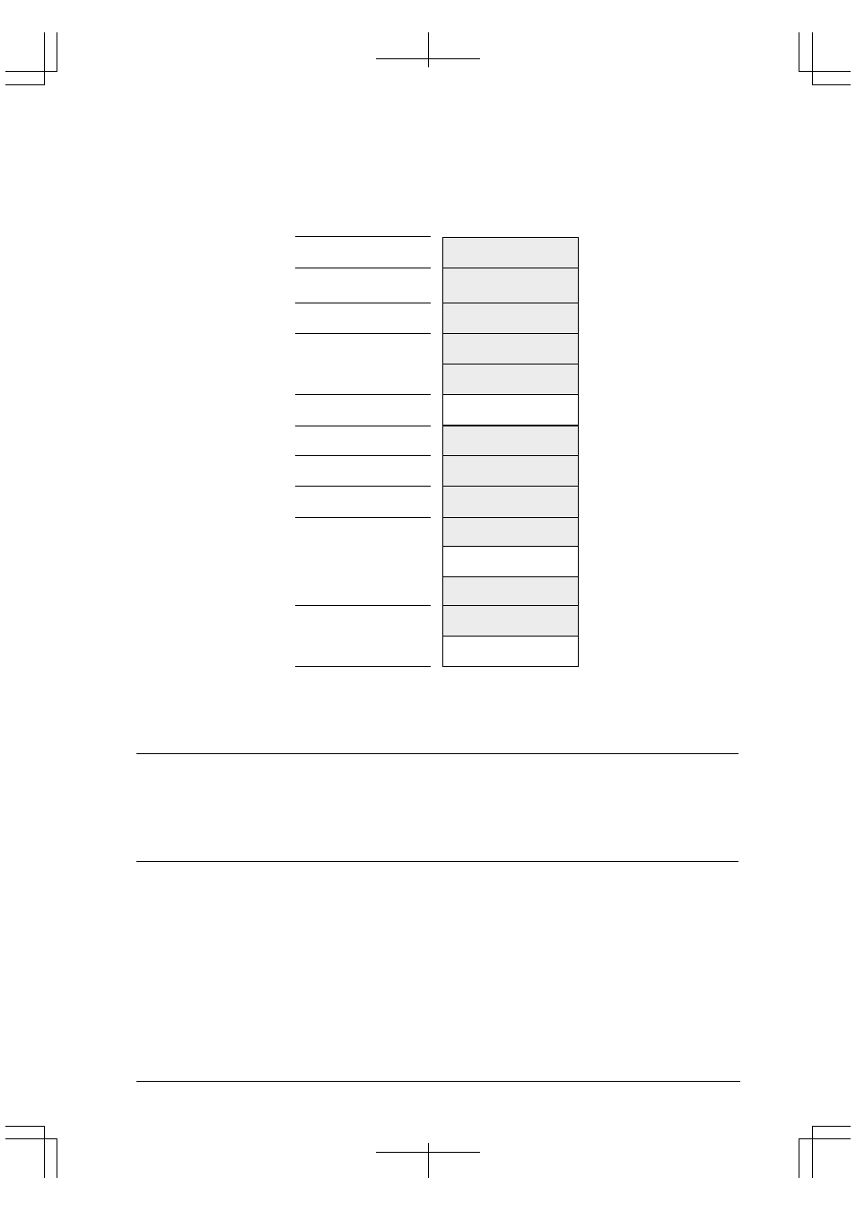
Figure 3.1 shows the S1C33210 memory map.
Areas 18
–
11
Area 10
Areas 9
–
7
Area 6
Area 5
Area 3
Area 2
Area 1
Area 0
0xFFFFFFF
0x1000000
0x0FFFFFF
0x0C00000
0x0BFFFFF
0x0400000
0x03FFFFF
0x0380000
0x037FFFF
0x0300000
0x02FFFFF
0x0200000
0x00FFFFF
0x0080000
0x007FFFF
0x0060000
0x005FFFF
0x0050000
0x004FFFF
0x0040000
0x003FFFF
0x0030000
0x002FFFF
0x0002000
0x0001FFF
0x0000000
S1C33210
External Memory
External Memory
External Memory
External I/O (16-bit device)
External I/O (8-bit device)
Area 4
0x01FFFFF
0x0100000
External Memory
(Reserved)
For middleware use
(Reserved)
For CPU, debug mode
Internal peripheral circuits
Internal peripheral circuits
(Mirror of internal
peripheral circuits)
(Mirror of internal
peripheral circuits)
(Mirror of internal RAM)
Internal RAM (8KB)
Area
Address
Figure 3.1 Memory Map
Area 2 is used in debug mode only and it cannot be accessed in user mode (normal program execution status).
3.1 ROM and Boot Address
The S1C33210 does not have a built-in ROM. The boot address is fixed at 0x0C00000, and so external ROM/Flash
should be used in Area 10.
For setting up Area 10, refer to the "BCU (Bus Controller Unit)" in "S1C33210 FUNCTION PART" in this manual.
3.2 RAM
The S1C33210 has a built-in 8KB RAM. The RAM is allocated to Area 0, address 0x0000000 to address
0x0001FFF.
The internal RAM is a 32-bit sized device and data can be read/written in 1 cycle regardless of data size (byte, half-
word or word).